13
To remove the shaft:
■ Stop the engine and remove the battery pack.
■ Loosen the knob by turning counter-clockwise.
■ Pull out the locking pin and remove the shaft.
WARNING
Never adjust the assist handle while the trimmer head is running. Failure to stop the engine may cause
serious personal injury.
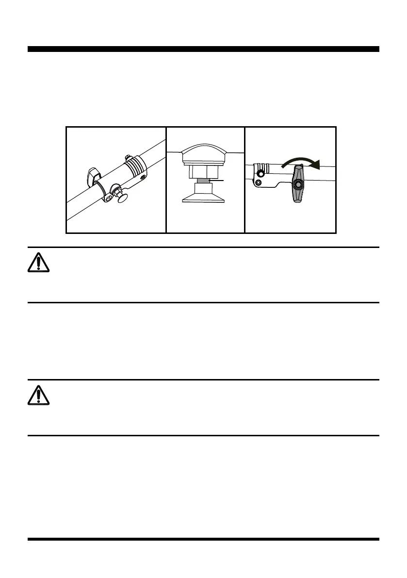
■ Release the locking pin. Rotate the shaft slightly to let the locking pin engage in the hole. Always ensure
the locking pin is locked into place (Fig. 5).
NOTE: If there is a gap between the locking pin and shaft connection sleeve, the shafts are not locked into
place (Fig. 6). Slightly rotate the shaft from side to side until the locking pin is locked into place.
■ Secure the shaft by turning the knob clockwise (Fig. 7).
ASSEMBLY
WARNING
Ensure that the knob is fully tightened before operating the tool; check it periodically for tightness
during use to avoid serious personal injury.
INSTALLING AND ADJUSTING THE ASSIST HANDLE (See Figs. 8-11)
■ Loosen the screws from the assist handle using the hex wrench provided.
■ Align the screw holes on the assist handle with the screw holes on the plate as shown (Fig. 8).
■ Tighten the screws moderately. Then adjust the assist handle to your desired position. The assist handle
can only be moved in the direction between the arrow marked "Handle Position" and shaft connection
sleeve (Fig. 9).
Fig. 5 Fig. 6
Fig. 7
Gap

 Loading...