- 9 -
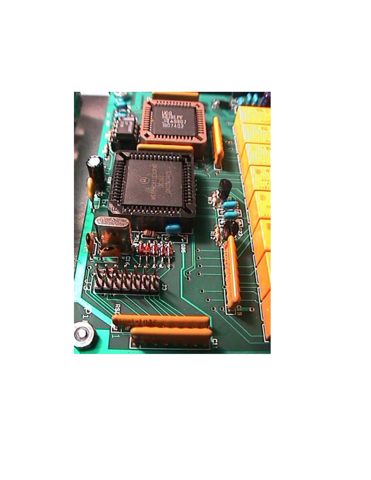
___ Install the relays K1-K17. Be careful not to bend the pins over pushing them in.
___ Install the 4.5 MHz crystal, X1.
___ Install the electrolytic capacitors, C9 10 uf radial and C18 1 uf radial. Note the polarity.
___ Install the 14 Pin header, J3. Solder the shorter ends of the pins to the PC board.
___ Install inductors L1-L8 on the PC board. Note that the mounting holes are offset slightly to help
keep the inductors straight after installation. Make sure the insulation is scraped off the ends of
the wires on each inductor. Push in each inductor until the windings touch the PC board. The #18
wire is stiff enough to support L5-L8, but RTV or hot melt glue may be needed for L1-L4 to hold
them in place. In you plan to use the unit in a mobile application, you should use the RTV or hot
melt glue on all inductors.