D
D
C
C
S
S
8
8
1
1
0
0
S
S
D
D
i
i
g
g
i
i
t
t
a
a
l
l
D
D
C
C
S
S
e
e
r
r
v
v
o
o
D
D
r
r
i
i
v
v
e
e
r
r
M
M
a
a
n
n
u
u
a
a
l
l
R
R
e
e
v
v
1
1
.
.
0
0
Tel: (86)755-26434369 3 Website: www.leadshine.com
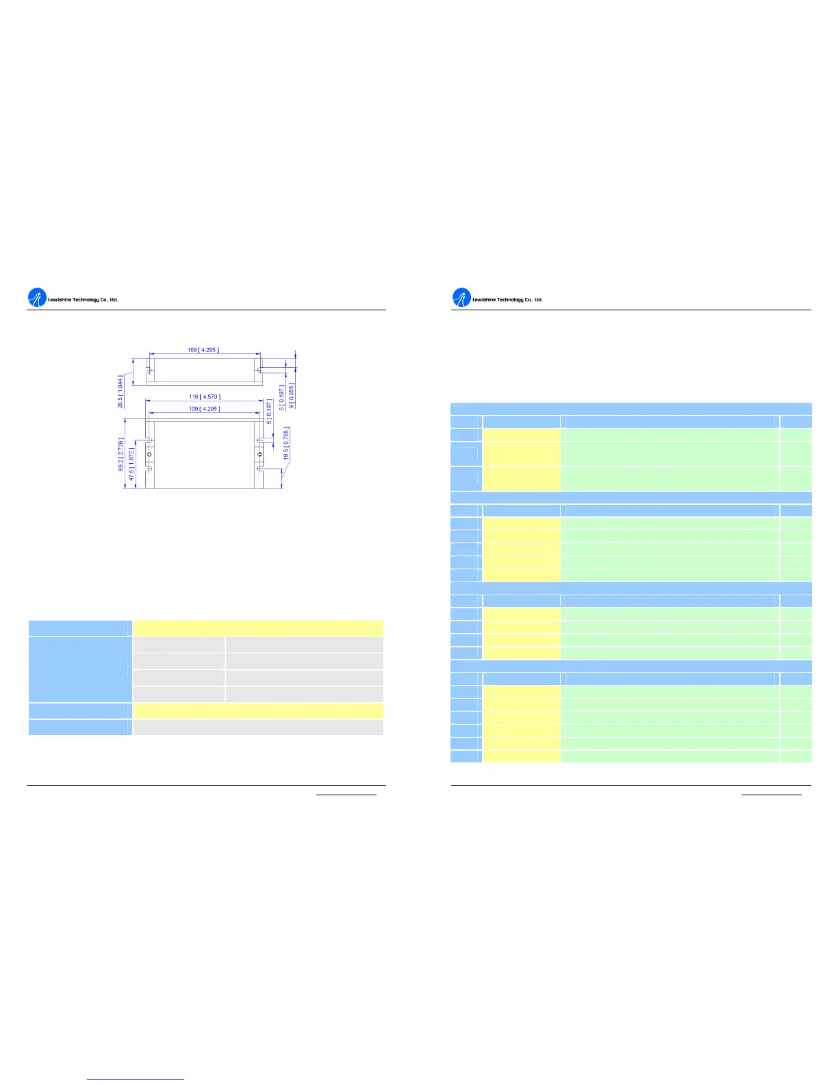
Mechanical Specifications (unit: mm[inch])
Figure 1: Mechanical specifications
Elimination of Heat
l Driver’s reliable working temperature should be <70℃(158℉), and motor
working temperature should be <80℃(176℉);
l It is recommended to mount the driver vertically to maximize heat sink area.
Operating Environment and Parameters
Cooling
Natural cooling or forced cooling
Environment
Avoid dust, oil fog and corrosive gases
Ambient Temperature
Vibration
5.9 m/s
2
Max
Storage Temperature
-20℃-65℃ (-4℉-149℉)
Weight
Approx. 210 g (7.4 oz)
D
D
C
C
S
S
8
8
1
1
0
0
S
S
D
D
i
i
g
g
i
i
t
t
a
a
l
l
D
D
C
C
S
S
e
e
r
r
v
v
o
o
D
D
r
r
i
i
v
v
e
e
r
r
M
M
a
a
n
n
u
u
a
a
l
l
R
R
e
e
v
v
1
1
.
.
0
0
Tel: (86)755-26434369 4 Website: www.leadshine.com
3. Connections
Connector Configuration
General information
Control Signal Connector
Pin Signal Description I/O
1 +5V Common +5V power input. I
2 PUL
Pulse control signal. See more information about PUL in “More
about +5V, PUL, DIR, ERR/RES Signals” section.
I
3 DIR
Direction control signal. See more information about DIR in “More
about +5V, PUL, DIR, ERR/RES Signals” section.
I
Encoder Signal Connector
Pin Signal Description I/O
1 EB Encoder channel B input. I
2 EA Encoder channel A input. I
3 E +5V Positive pole of the auxiliary power supply (50 mA (Max)). O
4 EGND Ground of the auxiliary power supply. GND
5 ERR/RES Alarm signal output(+5V) or restart signal input(+5V). O
Power Connector
Pin Signal Description I/O
1 Motor+ Motor positive connection. O
2 Motor- Motor negative connection. O
3 +VDC +18 TO 80VDC power input. I
4 GND Power ground. GND
RS232 Communication Connector
Pin Signal Description I/O
1 NC Not connected. -
2 +5V +5V power only for STU. O
3 TxD RS232 transmit. O
4 GND Ground. GND
5 RxD RS232 receive. I
6 NC Not connected. -