EasyManua.ls Logo

Leadshine Technology ACS806 User Manual

Leadshine Technology ACS806
33 pages
To Next Page IconTo Next Page
Page #1 background imageLoading...
Page #1 background image
Users Manual
For
ACS806
Digital AC Servo Drive
Revision 1.0
©2009 All Rights Reserved
Attention: Please read this manual carefully before using the drive!
3/F, Block 2, Nanyou Tianan Industrial Park, Nanshan Dist, Shenzhen, China
Tel: (86)755-26434369 Fax: (86)755-26402718
URL: www.leadshine.com E-Mail: sales@leadshine.com
The content in this manual has been carefully prepared and is believed to be accurate,
but no responsibility is assumed for inaccuracies.
Leadshine reserves the right to make changes without further notice to any products
herein to improve reliability, function or design. Leadshine does not assume any
liability arising out of the application or use of any product or circuit described
herein; neither does it convey any license under its patent rights of others.
Leadshines general policy does not recommend the use of its products in life
support or aircraft applications wherein a failure or malfunction of the product may
directly threaten life or injury. According to Leadshines terms and conditions of
sales, the user of Leadshines products in life support or aircraft applications
assumes all risks of such use and indemnifies Leadshine against all damages.
©2009 by Leadshine Technology Company Limited.
All Rights Reserved

Table of Contents

Question and Answer IconNeed help?

Do you have a question about the Leadshine Technology ACS806 and is the answer not in the manual?

Leadshine Technology ACS806 Specifications

General IconGeneral
Communication InterfaceRS232
FeedbackIncremental Encoder
Control ModePosition
Protection FeaturesOver-voltage, Over-current
Operating Temperature0°C to 50°C
Storage Temperature-20°C to 65°C
Input Voltage20-80 VDC
Microstep ResolutionProgrammable, 200~51200ppr
Pulse Input FrequencyUp to 200 kHz
WeightApprox. 0.5 kg

Summary

3. Connections

Connector Configuration

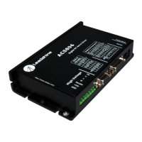
Overview of the various connectors on the ACS806 servo drive.

ENA, PUL, DIR Input Circuits and Connections

Wiring details for Enable, Pulse, and Direction input signals.

RL, FL Input Circuits and Connections

Wiring details for limit switch input circuits.

Pend, ALM Output Circuits and Connections

Wiring details for position and alarm output signals.

A+, A-, B+, B-, Z+, Z- Output Circuit

Output circuit for encoder feedback signals.

Encoder and Hall Sensor Connections

Wiring guidelines for encoder and Hall sensor feedback.

RS232 Interface Connection

Procedure for connecting the ACS806 via RS232 for communication.

4. Servo Setup

Install Encoder and Hall sensor

Instructions for installing encoder and hall sensor for motor feedback.

Prepare Power Supply

Guidelines for preparing and connecting the power supply.

Prepare Controller

Steps to prepare the motion controller for servo setup.

5. System Connections and Noise Prevention

6. Tuning the Servo

Testing the Servo

Initial steps to test the servo system before detailed tuning.

Tuning the Servo

Principles and methods for tuning servo system parameters for optimal performance.

7. PC window based Tuning Using ProTuner

ProTuner Installation

Step-by-step guide for installing the ProTuner software on a PC.

Current Loop Tuning

Procedure for tuning the current loop parameters of the servo drive.

Position Loop Tuning

Methods for tuning the position loop parameters for accurate motion control.

Servo Tuning Steps

Guided steps for performing servo tuning, including parameter adjustments.

8. Using Tips

10. Appendix

11. Contact Us

Technical Support

Contact information for technical assistance and support.

Related product manuals