A
A
C
C
S
S
8
8
0
0
6
6
D
D
i
i
g
g
i
i
t
t
a
a
l
l
A
A
C
C
S
S
e
e
r
r
v
v
o
o
d
d
r
r
i
i
v
v
e
e
M
M
a
a
n
n
u
u
a
a
l
l
R
R
e
e
v
v
1
1
.
.
0
0
Tel: (86)755-26434369 50 Website: www.leadshine.com
Position following Error Limit
The ACS806 will activate a position following error if position error between
command and encoder feedback exceeds the setting limit value. To set the limit
value, please select Tuning->PositionLoop->P_parameter and find the Position
FollowingErrLimit edit box. See figure 50.
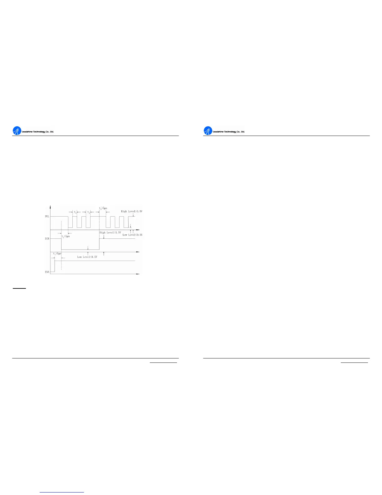
Sequence Chart of Control Signals
In order to avoid some fault operations and deviations, PUL, DIR and EN should
abide by some rules, shown as the following figure:
Figure51: Sequence chart of control signals
Notes:
a) t
1
: EN must be ahead of DIR by at least 5 µs. Usually, ENA is NC (not
connected). See Connections section for more information.
b) t
2
: DIR must be ahead of PUL active edge by at least 5 µs to ensure correct
direction.
c) t
3
: Pulse width not less than 0.85 µs;
d) t
4
: Low level width not less than 0.85 µs.
A
A
C
C
S
S
8
8
0
0
6
6
D
D
i
i
g
g
i
i
t
t
a
a
l
l
A
A
C
C
S
S
e
e
r
r
v
v
o
o
d
d
r
r
i
i
v
v
e
e
M
M
a
a
n
n
u
u
a
a
l
l
R
R
e
e
v
v
1
1
.
.
0
0
Tel: (86)755-26434369 51 Website: www.leadshine.com
Protection Functions
To improve reliability, the drive incorporates some built-in protection functions. The
ACS806 uses one RED LED to indicate what protection has been activated. The
periodic time of RED is 5 s (seconds), and how many times the RED turns on
indicates what protection has been activated. Because only one protection can be
displayed by RED LED, so the drive will decide what error to display according to
their priorities. See the following Protection Indications table for displaying
priorities.
Over-current Protection
Protection will be activated when continuous current exceeds 24A, and RED LED
will turn on once within each periodic time (5 s).
Over-voltage Protection
When power supply voltage exceeds 90±1.5 VDC, protection will be activated and
RED LED will turn on twice within each periodic time (5 s).
Under-voltage Protection
When power supply voltage is lower than 18±1.5 VDC, protection will be activated
and RED LED will turn on three times within each periodic time (5 s).
Phase Error Protection
Motor power lines wrong & not connected and encoder or hall sensor feedback
signals wrong connected will activate this protection. RED LED will turn on four
times within each periodic time (5 s).
Encoder or Hall Error Protection
No encoder feedback signals or wrong encoder/hall sensor feedback signals will
activate this protection. RED LED will turn on five times within each periodic time
(5 s).