A
A
C
C
S
S
8
8
0
0
6
6
D
D
i
i
g
g
i
i
t
t
a
a
l
l
A
A
C
C
S
S
e
e
r
r
v
v
o
o
d
d
r
r
i
i
v
v
e
e
M
M
a
a
n
n
u
u
a
a
l
l
R
R
e
e
v
v
1
1
.
.
0
0
Tel: (86)755-26434369 16 Website: www.leadshine.com
System Grounding
Good grounding practices help reduce the majority of noise present in a system. All
common grounds within an isolated system should be tied to PE (protective earth)
through a ‘SINGLE’ low resistance point. Avoiding repetitive links to PE creating
ground loops, which is a frequent source of noise. Central point grounding should also
be applied to cable shielding; shields should be open on one end and grounded on the
other. Close attention should also be given to chassis wires. For example, motors are
typically supplied with a chassis wire. If this chassis wire is connected to PE, but the
motor chassis itself is attached to the machine frame, which is also connected to PE, a
ground loop will be created. Wires used for grounding should be of a heavy gauge and
as short as possible. Unused wiring should also be grounded when safe to do so since
wires left floating can act as large antennas, which contribute to EMI.
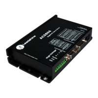
Power Supply Connection
NEVER connect power and ground in the wrong direction, because it will damage
the ACS806 drive. The distance between the DC power supply of the drive and the
drive itself should be as short as possible since the cable between the two is a source
of noise. When the power supply lines are longer than 50 cm, a 1000µF/100V
electrolytic capacitor should be connected between the terminal “GND” and the
terminal “+VDC”. This capacitor stabilizes the voltage supplied to the drive as well
as filters noise on the power supply line. Please note that the polarity can not be
reversed.
It is recommended to have multiple drives to share one power supply to reduce cost if
the supply has enough capacity. To avoid cross interference, DO NOT daisy-chain
the power supply input pins of the drives. Instead, please connect them to power
supply separately.
A
A
C
C
S
S
8
8
0
0
6
6
D
D
i
i
g
g
i
i
t
t
a
a
l
l
A
A
C
C
S
S
e
e
r
r
v
v
o
o
d
d
r
r
i
i
v
v
e
e
M
M
a
a
n
n
u
u
a
a
l
l
R
R
e
e
v
v
1
1
.
.
0
0
Tel: (86)755-26434369 17 Website: www.leadshine.com
5. Tuning the Servo
Testing the Servo
You may wish to secure the motor so it can’t jump off the bench. Turn on the power
supply, the green (Power) LED will light. The ACS806 has default parameters stored
in the drive. If the system has no hardware and wirings problem, the motor should be
locked and the drive should be ready.
If the motor jumps slightly and the red LED immediately turns on (flickers), then
either the motor or the encoder is wired in reversal. Open the tuning software
ProTuner and check drive status by clicking Err_check. If it’s Phase Error, then
reversal motor wires or exchange encoder inputs and try again. If it’s Encoder Error,
please check encoder and its wirings, and then try again. If it still doesn’t work after
you followed all of the previous steps, please contact us at tech@leadshine.com.
If the red LED is off and the motor is normal, then you can start to tune the servo
with selected tool. PC based tuning software ProTuner and handheld small servo
tuning unit STU are available for the ACS806.
Tuning the Servo
A servo system is error-driven. The “Gain” of the system determines how hard the
servo tries to reduce the error. A high-gain system can produce large correcting
torques when the error is very small. A high gain is required if the output is required
to follow the input faithfully with minimal error.
A servo motor and its load both have inertia, which the servo amplifier must
accelerate and decelerate while attempting to follow a change at the input. The
presence of the inertia will tend to result in over-correction, with the system
oscillating beyond either side of its target. It’s called UNDER DAMPED status. See
Figure 11. This oscillation must be damped, but too much damping will cause the