A
A
C
C
S
S
8
8
0
0
6
6
D
D
i
i
g
g
i
i
t
t
a
a
l
l
A
A
C
C
S
S
e
e
r
r
v
v
o
o
d
d
r
r
i
i
v
v
e
e
M
M
a
a
n
n
u
u
a
a
l
l
R
R
e
e
v
v
1
1
.
.
0
0
Tel: (86)755-26434369 10 Website: www.leadshine.com
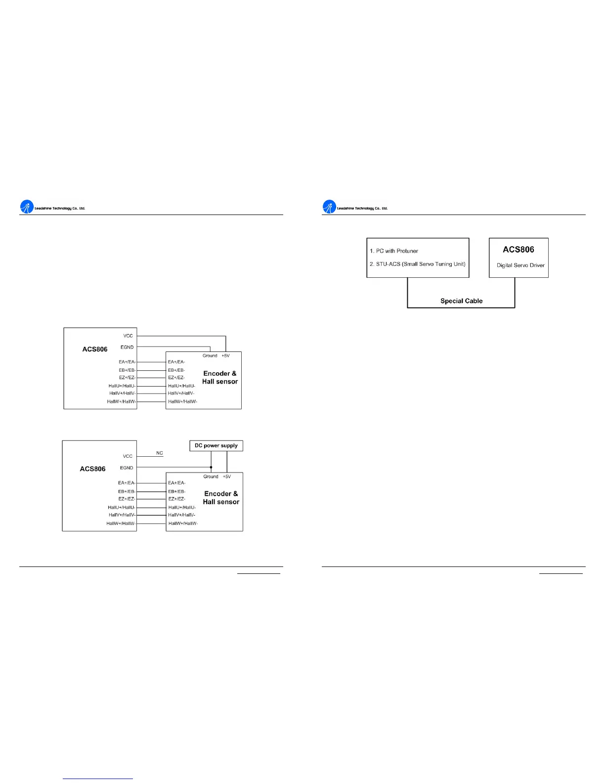
Encoder and Hall Sensor Connections
The ACS806 can accept both incremental encoder and Hall Effect sensor inputs for
motor shaft position feedbacks. Note that twisted-pair shielded cabling provides the
best immunity in electrically noisy environments.
The ACS806 has the +5V power to supply the encoder & hall sensor. If the encoder
and hall sensor drains less than 100mA, the ACS806 can supply them directly, and
connect it as Figure 7. If the encoder drains more than 50mA, use an external DC
supply and connect it as Figure 8.
Figure 7: The ACS806 supplies the encoder directly
Figure 8: Using external DC power supply to supply the encoder
A
A
C
C
S
S
8
8
0
0
6
6
D
D
i
i
g
g
i
i
t
t
a
a
l
l
A
A
C
C
S
S
e
e
r
r
v
v
o
o
d
d
r
r
i
i
v
v
e
e
M
M
a
a
n
n
u
u
a
a
l
l
R
R
e
e
v
v
1
1
.
.
0
0
Tel: (86)755-26434369 11 Website: www.leadshine.com
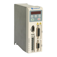
RS232 Interface Connection
Figure 9: RS232 interface connection
Typical Connections
A typical connection of the ACS806 is shown as Figure 10. Please consult “Digital
and Analog I/O” and “Encoder and hall sensor Connections” for more information
about controller and encoder connections.