A
A
C
C
S
S
8
8
0
0
6
6
D
D
i
i
g
g
i
i
t
t
a
a
l
l
A
A
C
C
S
S
e
e
r
r
v
v
o
o
d
d
r
r
i
i
v
v
e
e
M
M
a
a
n
n
u
u
a
a
l
l
R
R
e
e
v
v
1
1
.
.
0
0
Tel: (86)755-26434369 52 Website: www.leadshine.com
Limit Error Protection
Protection will be activated when the positive or negative limit input in FL or RL pin
is active. RED LED will turn on six times within each periodic time (5 s).
Position Following Error Protection
When position following error reaches Position Following Error Limit parameter
setting in the drive, this protection will be activated. RED LED will turn on seven
times within each periodic time (5 s). Note that wrong motor connection will cause
this protection too. Please check your motor connection if this protection is activated
at the startup.
Attention: Since there is no protection against power leads (﹢,﹣) reversal, it is
critical to make sure that power supply leads correctly connected to drive. Otherwise,
the drive will be damaged instantly.
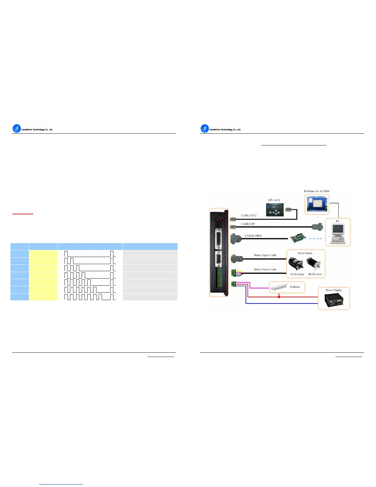
Protection Indications
c Time(s) of ON Sequence wave of RED LED Description
1
st
1
Over-current protection
2
nd
2
Over-voltage protection
3
rd
3
Under-voltage protection
4
th
4
Phase error protection
5
th
5
Encoder or Hall error protection
6
th
6
Limit error protection
7
th
7
Position following error protection
Maximum Pulse Input Frequency
Maximum Pulse Input Frequency is the highest frequency at which the drive can
interpret encoder feedback. To convert this frequency to RPM, use the following
formula:
A
A
C
C
S
S
8
8
0
0
6
6
D
D
i
i
g
g
i
i
t
t
a
a
l
l
A
A
C
C
S
S
e
e
r
r
v
v
o
o
d
d
r
r
i
i
v
v
e
e
M
M
a
a
n
n
u
u
a
a
l
l
R
R
e
e
v
v
1
1
.
.
0
0
Tel: (86)755-26434369 53 Website: www.leadshine.com
resolutionperPulse
FrequenceInputPulseMax
RPM
60)(
(max)
×
=
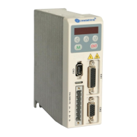
8. Accessories
ACS806 Accessories and Connections
Figure 52: ACS806 accessories and connections