A
A
C
C
S
S
8
8
0
0
6
6
D
D
i
i
g
g
i
i
t
t
a
a
l
l
A
A
C
C
S
S
e
e
r
r
v
v
o
o
d
d
r
r
i
i
v
v
e
e
M
M
a
a
n
n
u
u
a
a
l
l
R
R
e
e
v
v
1
1
.
.
0
0
Tel: (86)755-26434369 4 Website: www.leadshine.com
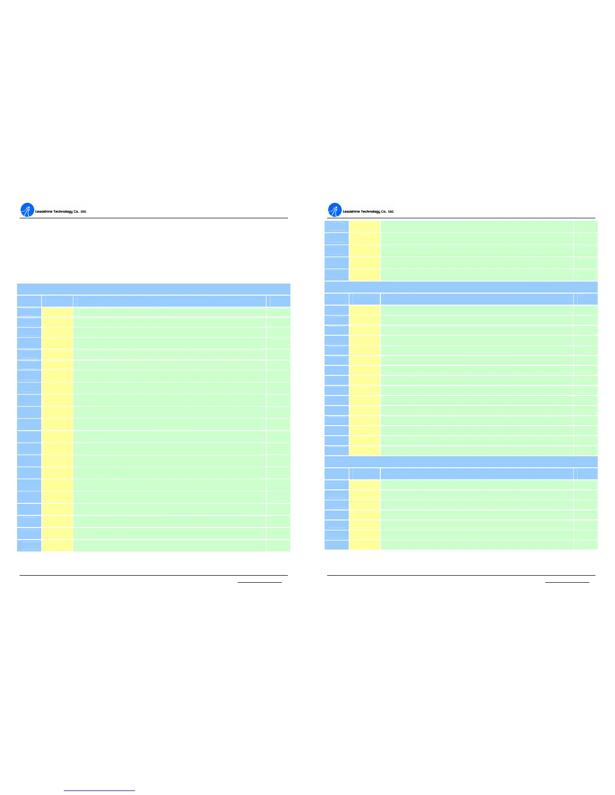
3. Connections
Connector Configuration
General Information
Digital & Analog I/O Connector
Pin Signal Description I/O
1 ENA+ Enable signal input +
I
2 ENA- Enable signal input -
I
3 PUL+ Pulse signal input +
I
4 PUL- Pulse signal input -
I
5 DIR+ Direction signal input +
I
6 DIR- Direction signal input -
I
7 FL
Positive limit signal input
I
8 RL
Negative limit signal input
I
9 SGND
Signal ground
GND
10 Pend+
In position signal output+
O
11 Pend-
In position signal output-
O
12 ALM+
Alarm output signal+
O
13 ALM-
Alarm output signal-
O
14 NC
Not connected
-
15 NC
Not connected
-
16 NC
Not connected
-
17 FG
Ground terminal for shield
GND
18 SGND
Signal ground
GND
19 +5V
+5V@10mA power supply
O
20 A+
Encoder channel A+ output
O
21 A-
Encoder channel A- output
O
A
A
C
C
S
S
8
8
0
0
6
6
D
D
i
i
g
g
i
i
t
t
a
a
l
l
A
A
C
C
S
S
e
e
r
r
v
v
o
o
d
d
r
r
i
i
v
v
e
e
M
M
a
a
n
n
u
u
a
a
l
l
R
R
e
e
v
v
1
1
.
.
0
0
Tel: (86)755-26434369 5 Website: www.leadshine.com
22 B+
Encoder channel B+ output
O
23 B-
Encoder channel B- output
O
24 Z+
Encoder channel Z+ output
O
25 Z-
Encoder channel Z- output
O
26 SGND
Signal ground
GND
Halls & Encoder Connector
Pin Signal Description I/O
1 EA+ Encoder channel A+ input I
2 EB+ Encoder channel B+ input I
3 EGND
Hall sensor W+ input I
5 HallU+
Hall sensor U+ input I
6 FG Ground terminal for shielded GND
7 EZ+ Encoder channel Z+ input I
8 EZ- Encoder channel Z- input I
9 HallV+
Hall sensor V+ input I
10 HallV- Hall sensor V- input I
11 EA- Encoder channel A- input I
12 EB- Encoder channel B- input I
13 VCC +5V @ 100 mA max. O
14 HallW-
Hall sensor W- input I
15 HallU-
Hall sensor U- input I
High Voltage Connector
Pin Signal Description I/O
1 PE Motor case ground
GND
2 U Motor phase U
O
3 V Motor phase V
O
4 W Motor phase W
O
5 Rbrake
Brake resistor connection (VDC-RBrake)
I
6 +Vdc DC power Input (18-80VDC)
I
7 GND Power Ground.
GND