High Voltage Digital Stepper Drive 3DM2283 Manual
Page
4
of
7
Protection Indications
The green indicator turns on at power-up. When drive protection is activated, the red LED blinks periodicity to indicate the error type
Over-voltage Protection,over 440VDC
Pin Assignment
The 3DM2283 has one barrier strip connector for power and motor connections and one screw terminal for control signal connections.
Power and Motor Connector
Recommend connect this port to the ground for better safety.
Power supply inputs. If AC input, recommend use isolation transformers with
theoretical output voltage of 150-220VAC.
Pin Assignment (Continued)
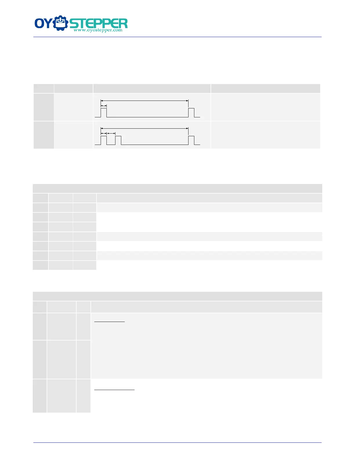
Pulse Signal: In single pulse (pulse/direction) mode, this input represents pulse signal, each
rising or falling edge active (software configurable, see DM drives software operational
manual for the detail); In double pulse mode (software configurable), this input represents
clockwise (CW) pulse, active both at high level and low level. 4-5V when PUL-HIGH,
0-0.5V when PUL-LOW. For reliable response, pulse width should be longer than 2.5μs.
Series connect resistors for current-limiting when +12V or +24V used. The same as DIR
and ENA signal.
Direction Signal: In single-pulse mode, this signal has low/high voltage levels, representing
two directions of motor rotation. In double-pulse mode (software configurable), this signal
is counter-clock (CCW) pulse, active both at high level and low level. For reliable motion