The Leadshine HBS Series Hybrid Servo is a cost-effective alternative to traditional servo systems, designed for applications requiring high performance and reliability. It combines the best aspects of both servo and stepper motor technologies, offering unique capabilities and enhancements. The system consists of a hybrid servo motor integrated with a fully digital, high-performance easy servo drive. An internal encoder is crucial for real-time closing of position, velocity, and current loops, similar to how servo systems operate.
Function Description:
The HBS hybrid servo drive functions by taking a command position, comparing it with the measured position from the encoder, and then using an amplifier to drive the stepper motor. This closed-loop control ensures precise positioning and movement. The drive accepts Pulse/Direction or CW/CCW control signals, ranging from 5V to 24V. Its differential signal input allows interfacing with both PNP (sourcing) and NPN (sinking) type control signals from a controller. For the enable signal, applying 0V between ENA+ and ENA- or leaving them unconnected enables the drive. The drive also provides ALM (alarm) and in-position (Pend+/Pend-) output signals. The ALM signal indicates error status, while the in-position signal confirms that the motor has reached its target position. These are Open Collector (OC) outputs, capable of sinking or sourcing 50mA current.
The HBS drive can be configured using PC software, which communicates via an RS232 serial port or a USB-RS232 converter. This software, called ProTuner, allows users to set various parameters, perform motor tests, and even rotate the motor without a dedicated motion controller. This feature is particularly useful for initial setup and verification. The drive also supports configuration via DIP switches for certain models (HBS86 and HBS86H) to set micro-step resolution and direction polarity.
Important Technical Specifications:
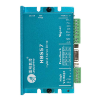
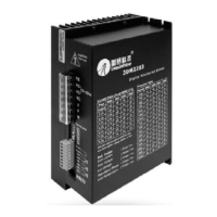
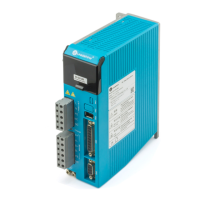
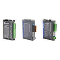
The HBS series includes models like HBS57, HBS86, and HBS86H, each designed for specific motor types and voltage ranges.
- Micro Step Resolution (PPR):
- HBS57: 4000 (Software configured)
- HBS86, HBS86H: 1600 (DIP Switch configured), with options for 800, 3200, 6400, 12800, 25600, 51200, 1000, 2000, 4000, 5000, 8000, 10000, 20000, 40000 steps per revolution.
- Holding Current Percentage (%): 60% (Software configured)
- Close-loop Current Limit Percentage (%): 100% (Software configured)
- Current Loop Kp/Ki:
- HBS57: Auto Tuning At Power-up
- HBS86, HBS86H: 1500/200 (Software configured)
- Recommended Kp/Ki values vary based on motor and supply voltage (e.g., for 57HS10-EC-XXXX with HBS86 at 24VDC, Kp/Ki is 1500/200; at 36VDC, 1000/300; at 48VDC, 800/250).
- Applied Motor:
- HBS57: 573S09-EC-XXXX, 573S20-EC-XXXX
- HBS86, HBS86H: 86HS80-EC-XXXX, 86HS40-EC-XXXX
- Matching Supply Voltage:
- HBS57: 24-36VDC
- HBS86, HBS86H: 60-100VDC
- Specific recommendations for motors: 57HS09-EC-XXXX (HBS57) at DC 24V; 57HS20-EC-XXXX (HBS57) at DC 36V; 57HS10-EC-XXXX (HBS86) at DC 36V; 57HS20-EC-XXXX (HBS86) at DC 36V; 86HS40-EC-XXXX (HBS86) at DC 60V; 86HS80-EC-XXXX (HBS86) at DC 60V.
- Control Signal Frequency: 200K for HBS57 and HBS86(H).
- Control Signal Setup Timing:
- Direction Setup Time (tDS): >50uS
- Pulse High/Low Level Setup Time (tPHS/tPLS): >2.5us
- Direction Delay Time (tDD): >50uS
- Enable Setup Time (tES): >200ms
- Enable Delay Time (tED): >200ms
Usage Features:
- Easy Start-up: For initial evaluation, only an HBS drive, a hybrid motor (stepper drive with encoder), and a power supply are needed. A pulse generator, PLC, or motion controller is recommended for full functionality verification.
- Flexible Connectivity: Connects to PC via RS232 cable or USB-RS232 converter for software configuration and motor testing.
- Motor and Power Supply Connection: Simple 6-pin pluggable screw connector for both power supply (+Vdc, GND) and motor (A+, A-, B+, B-) connections.
- Encoder Feedback: Essential for closed-loop operation. HBS57 encoder output connects directly, while HBS86/HBS86H require an extension/conversion cable from HDD15 to screw terminal.
- Rotation Speed and Angle Calculation: Formulas are provided to calculate motor rotation speed (RPM) and angle (°) based on pulse frequency and counts, and micro-step resolution.
- PC Software Motor Control: The ProTuner software includes an emulating controller for self-testing and basic motor rotation, allowing users to define trapezoidal velocity profiles.
- Power Supply Selection Guidance: Detailed advice on choosing between regulated and unregulated power supplies, considering factors like current rating, motor speed, noise, and heating. Recommendations for multiple drives sharing a single power supply are also provided.
- Fine Tuning: Default current and position loop parameters are optimized for most industrial applications, but ProTuner software allows for fine-tuning for specific needs.
Maintenance Features:
- Protection Functions: Built-in protection mechanisms enhance reliability.
- Over-current Protection: Activated when continuous current exceeds limits or in case of short circuits. Indicated by the red LED blinking once per 4-second cycle.
- Over-voltage Protection: Activated when power supply voltage exceeds limits. Indicated by the red LED blinking twice per 4-second cycle.
- Position Following Error Protection: Activated when the position error exceeds a configurable limit. Indicated by the red LED blinking seven times per 4-second cycle.
- Troubleshooting Guide: A comprehensive FAQ section helps identify and resolve common issues, categorizing problems into electrical or mechanical nature, and providing possible causes for symptoms like motor not rotating, rotating in the wrong direction, drive fault, erratic motion, or excessive heating.
- Wiring Notes for Reliability:
- Use twisted shielded pair cables for control signals to improve anti-interference.
- Separate pulse/direction signal wires from motor wires by at least 10 cm to prevent noise interference.
- Connect multiple drives to a power supply separately, rather than daisy-chaining, to avoid cross-interference.
- Critical Safety Warning: Never connect or disconnect power connectors while the drive is powered ON to prevent high back-EMF voltage surges that can damage the drive. Ensure correct power lead polarity as there is no protection against reversal.
- Warranty and Service: Leadshine offers a 12-month warranty against material and workmanship defects. Procedures for obtaining warranty service, including RMA (Returned Material Authorization) and shipping failed products, are outlined. Exclusions from warranty coverage include damage due to improper handling, wiring, unauthorized modification, misuse, or operation outside electrical or environmental specifications.