Hybrid Servo Hardware Installation Manual
12
Recommended Supply Voltage
Both Leadshine’s regulated and unregulated power supply has been designed specially for motion
control.
Motor Drive Voltage Range
Typical Voltage
Leadshine Power Supply
57HS09-EC-XXXX
HBS57
DC(20-50)V DC 24V RPS2410(-L)
57HS20-EC-XXXX
HBS57
DC(20-50)V DC 36V RPS369
57HS10-EC-XXXX
HBS86
DC(30-80)V DC 36V RPS369
57HS20-EC-XXXX
HBS86
DC(30-80)V DC 36V RPS369
86HS40-EC-XXXX
HBS86
DC(30-80)V DC 60V RPS608
86HS80-EC-XXXX
HBS86
DC(30-80)V DC 60V RPS608
Control Signal Wiring
The HBS drive accepts both differential and single-ended control signals (including open-collector and
PNP output). Make sure the output port of the controller can sink or source 10mA at the least. If
you encounter the problem that motor does not rotating or losing steps, check whether or not the
controller can maintain 5V/24V output at any current and pulse frequency.
If the cable length is greater than 50cm, it is recommended to use twisted shielded pair cable for
these signal. Do not put the control signal cable together with the cables which is used for high
power or high current equipment, in case of electronic interference coupled into the control signal.
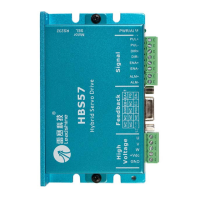
NPN (Sinking) Control Signal Wiring
If the motion controller is not differential output type, NPN type is recommended as it can sink more
current than PNP type. In this wiring, Pulse, Direction and Enable signal share the same VCC (positive)
terminal.
Drive
PUL+
DIR+
PUL-
DIR-
Pulses
ENA+
ENA-
Direction
Enable
VCC
5-24V
Controller