Do you have a question about the Leadshine 3DM2283 and is the answer not in the manual?
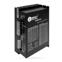
Details the 3DM2283 as a high voltage, digital stepper drive with advanced DSP control.
Lists suitable applications for the 3DM2283, including laser cutters and CNC routers.
Details electrical parameters such as input voltage, pulse frequency, and logic signal current.
Covers cooling, storage, ambient temperature, and humidity requirements for operation.
Provides mechanical dimensions and weight information for the 3DM2283 drive.
Describes LED indicators for drive protection states like over-current and over-voltage.
Details the pins for power supply and motor phase connections (U, V, W).
Explains pins for pulse, direction, and enable signals for motor control.
Details the RS232 port for configuring drive parameters like current and microstep.
Provides DIP switch settings for dynamic current (peak and RMS) for different current levels.
Explains the function of SW4 for reducing motor current when idle.
Details DIP switch settings (SW5-SW8) for microstep resolution from 200 to 10000.
Describes how to activate auto-configuration using SW4 for current loop parameters.
Illustrates typical wiring for NPN control signals from a controller to the drive.
Shows a diagram for connecting the 863SXX motor phases (U, V, W) to the drive.
The 3DM2283 is a 3-phase digital stepper drive designed for high-voltage applications, offering advanced DSP control algorithms for smooth and precise motor movement. It features auto-identification and parameter auto-configuration technology, allowing for optimal performance with various motors and simplifying setup.
The 3DM2283 is a high-voltage, fully digital stepper drive that utilizes advanced DSP control algorithms to achieve a unique level of system smoothness, optimal torque, and effective nulling of mid-range instability. Its motor auto-identification and parameter auto-configuration feature enables quick setup to optimal modes with different motors. This drive is designed to operate with 3-phase stepper motors and supports both PUL/DIR (pulse/direction) and CW/CCW (clockwise/counter-clockwise) modes.
Electrical Specifications:
Microstep Resolution: The drive offers a wide range of microstep resolutions, from full-step (200 steps/revolution) up to 51,200 steps/revolution, configurable via DIP switches (SW5-SW8). This allows for smoother motor movement, especially at low speeds.
Dynamic Current Settings (Peak/RMS):
Physical Specifications:
Auto-Configuration: The drive features motor auto-identification and parameter auto-configuration technology. This allows the drive to automatically identify motor parameters and calculate optimal current loop parameters, providing optimal responses with different motors. This process is activated by switching SW4 two times within two seconds (OFF-ON-OFF or ON-OFF-ON) and typically takes 1 to 3 seconds, during which the motor shaft may vibrate slightly.
Multi-Stepping: Multi-Stepping functionality enables a low-resolution step input to produce a higher microstep output, resulting in smoother motor movement and reduced vibration.
Soft-Start: The 3DM2283 incorporates a soft-start feature, eliminating any "jump" when the device is powered on, ensuring a smooth and controlled startup.
Idle-Current Reduction: The drive supports automatic idle-current reduction, which can be configured via software. DIP switch SW4 determines whether current reduction is performed when no pulse is applied to the drive. When set to OFF, motor current reduces automatically; when set to ON, motor current remains the same as the dynamic current. This feature helps in reducing motor heating and energy consumption during idle periods.
Control Signal Input: The drive uses 5V optically isolated inputs for control signals (PUL+, PUL-, DIR+, DIR-, ENA+, ENA-). For reliable response, pulse width should be longer than 2.5µs. Series resistors are recommended for current-limiting when using +12V or +24V control signals. The DIR signal should precede the PUL signal by at least 5µs for reliable motion. The polarity of the direction and enable signals is software configurable.
RS232 Communication Port: An RS232 communication port is provided for configuring various parameters such as peak current, microstep resolution, active level, current loop parameters, and anti-resonance parameters using dedicated software.
Compatibility: Suitable for a wide range of 3-phase stepper motors, typically from NEMA size 34 to 51.
Applications: The 3DM2283 is ideal for high-requirement applications that demand both low-speed smoothness and high-speed performance. Common applications include laser cutters, laser markers, high-precision X-Y tables, labeling machines, and CNC routers.
Protection Indications: The drive includes built-in protection mechanisms. A green LED indicator turns on at power-up. If a protection event is triggered, a red LED will blink periodically to indicate the error type:
Protections: The 3DM2283 incorporates several protection features to ensure reliability and longevity:
Fault Signal Output: A FAULT+ / FAULT- OC (Open Collector) output signal is active when any of the protection mechanisms (over-voltage, over-current, low voltage, phase error, over-temperature) are triggered. This port can sink or source 20mA current at 24V. In normal operation, the resistance between FAULT+ and FAULT- is high impedance, becoming low when the 3DM2283 enters an error state.
Cooling: The drive can operate with natural cooling or forced cooling, depending on the application environment and heat dissipation requirements. The operating environment should avoid dust, oil fog, and corrosive gases.
Environmental Conditions:
Grounding: It is recommended to connect the PE (Protective Earth) port to ground for better safety.
| Brand | Leadshine |
|---|---|
| Model | 3DM2283 |
| Category | Servo Drives |
| Language | English |