Hybrid Servo Hardware Installation Manual
2
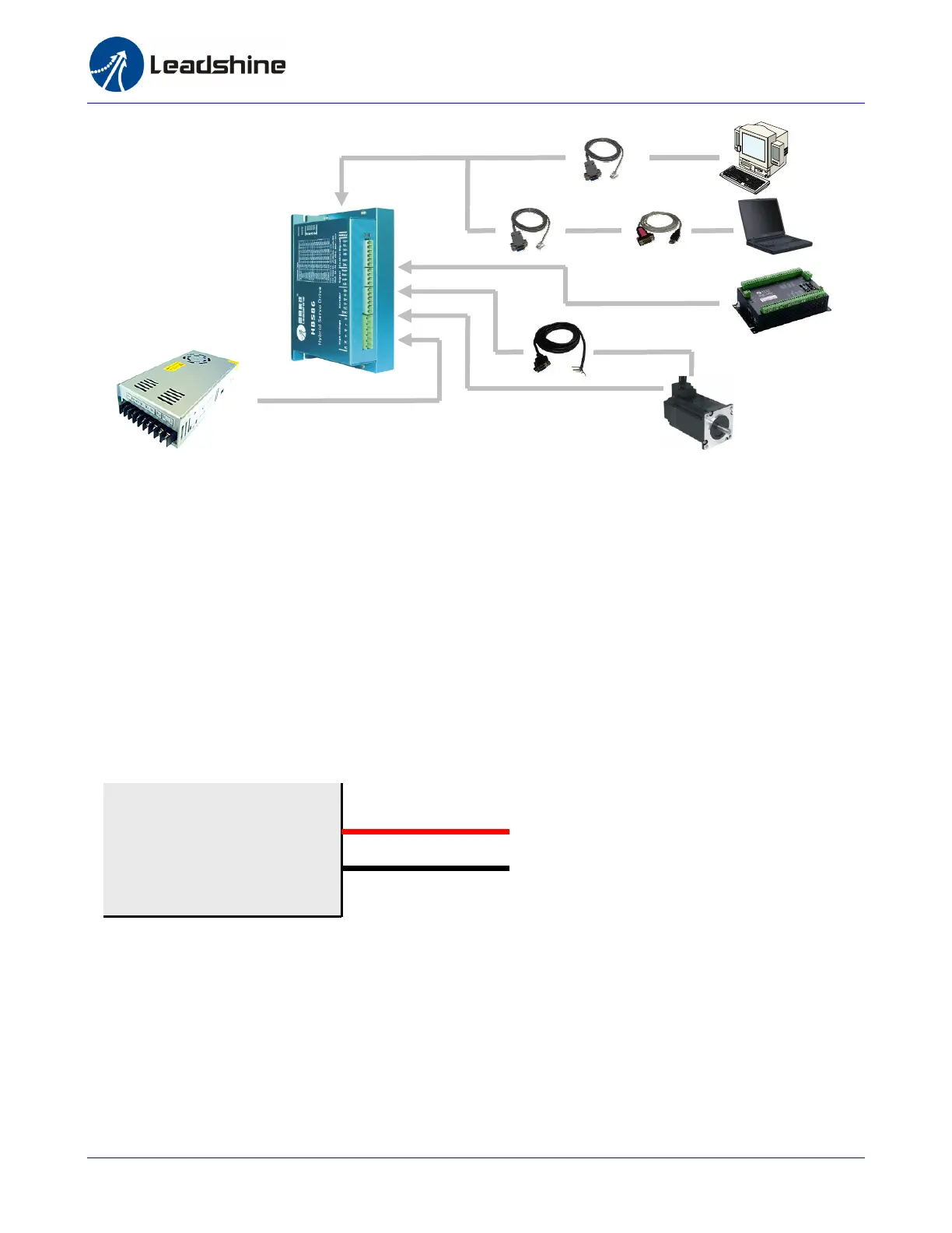
Connecting Power Supply
Power supply connection is the simplest thing through this manual because it has only tow wires:
positive wire and negative wire. However you should caution the incorrect connection polarity. The
HBS drive a 6-pin pluggable screw connector that is used for both power supply connection and
motor connection. Looking at the drive cover you should find the printed “+Vdc” and “GND” symbol.
Connect the positive wire to “+Vdc” terminal and connect the negative wire to “GND” terminal. Note
that the power should be off when you make the above connection.
Note: Do not exceed the input voltage range of the HBS drive. Please consult Power Supply
Selection chapter for the recommended supply voltage.
Connecting Motor
The HBS motor has 4 wires: A+, A-, B+ and B-. Just connect them to the corresponding terminals of
the HBS drive. Refer to the HBS drive or the HBS motor datasheet for the detailed motor specification
and wiring diagram.
+Vdc
GND
High Voltage
+ (Positive)
Or
RS232 Cable
USB-232 Converter
Motion Controller
Encoder Cable
Motor Power Cable
Power Supply