Do you have a question about the Leadshine iSV-B23 Series and is the answer not in the manual?
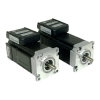
The Leadshine iSV-B23xxx is an integrated BLDC servo motor, a compact and efficient solution for various motion control applications. This device combines a NEMA 23 brushless motor, a 1,000-line (4,000 PPR) encoder, and a servo drive into a single unit. This integration offers several advantages, including significant space savings, reduced wiring time for encoder connections and motor leads, minimized interference, and lower overall cable and labor costs. The iSV-B23xxx is designed to provide smooth low-speed performance, making it an ideal choice for applications where both precision and a small footprint are critical.
The iSV-B23xxx operates as a closed-loop servo system, where the motor's position is continuously monitored and adjusted to match the commanded position. The integrated design simplifies the overall system architecture by eliminating the need for separate motor, encoder, and drive components.
Core Components:
Control Modes: The iSV-B23xxx can be configured and controlled in several ways:
Input/Output Signals:
Getting Started: To begin using the iSV-B23xxx, you need the integrated servo motor, a DC power supply, and optionally a motion controller or a PC with ProTuner software.
Power Supply Connection: The iSV-B23xxx accepts DC power input. A 2-pin pluggable screw connector is used for power supply connections. It's crucial to observe correct polarity, connecting the positive wire to the "+Vdc" terminal and the negative wire to the "GND" terminal. The power supply should always be switched off when making connections. Users must ensure the input voltage does not exceed the motor's specified range.
Motion Controller Connection: The pulse, direction, and enable inputs are differential and can be connected to NPN (sinking), PNP (sourcing), or differential type controllers. For NPN (sourcing) controllers, control signals share a common positive VCC. For PNP (sinking) controllers, control signals refer to the same ground terminal.
PC Connection: An RS232 communication port is built into the drive for configuration and control via PC software (ProTuner). A 5-pin plug-in terminal block on the drive connects to a 9-pin D-Sub female connector on the PC via an RS232 cable. If the PC lacks a serial port, a USB-to-Serial converter is required. As with power connections, the device should be powered off when connecting or disconnecting the RS232 cable.
Configuration:
Calculating Rotation Speed and Angle: Users can calculate the motor's rotation speed (RPM) and angle (degrees) based on the pulse frequency and pulse counts, using provided formulas:
Rotating the iSV Motor:
Power Supply Selection: Choosing an appropriate power supply is crucial for optimal performance.
Wiring Notes:
Control Signal Setup Timing: For reliable operation and to prevent step loss, control signals (Pulse, Direction, Enable) must meet specific setup time requirements. These include Direction Setup Time (tDS), Pulse High/Low Level Setup Time (tPHS/tPLS), Direction Delay Time (tDD), Enable Setup Time (tES), and Enable Delay Time (tED). Specific values for these timings are provided for different iSV-B23xxx models.
Fine Tuning: While Leadshine pre-loads optimized default parameters for current and position loops, users may need to fine-tune the position loop parameters for their specific application to achieve the best performance. This tuning depends on factors such as power supply voltage, load inertia, and motion profile.
Protection Functions & Indications: The iSV-B23xxx incorporates several built-in protection functions indicated by a red LED, which blinks periodically (4-second cycle). The number of blinks signifies the type of protection activated, with higher priority errors being displayed first.
Resetting Protection: When protection functions are active, the motor shaft will be free, and the LED will blink. To restore proper function, the drive must be repowered after resolving the underlying problem.
Important Safety Note: There is no protection against power lead polarity reversal. Incorrectly connecting the power supply leads can instantly damage the drive. It is critical to double-check power connections before applying power.
Troubleshooting: In case of improper operation, the first step is to determine if the problem is electrical or mechanical. Then, isolate the problematic system component. Documenting each troubleshooting step is important for future reference and for assisting technical support. Many issues often stem from electrical noise, controller software errors, or incorrect wiring.
Warranty and Service: Leadshine Technology Co., Ltd. provides a 12-month warranty against defects in materials and workmanship from the shipment date. During this period, Leadshine will repair or replace defective products at its discretion. The warranty does not cover damage due to improper handling, inadequate wiring, unauthorized modification, misuse, or operation outside electrical or environmental specifications.
To obtain warranty service, customers must acquire a Returned Material Authorization (RMA) number from customer service via email before returning the product. Customers are responsible for prepaying shipping charges for products sent to Leadshine for warranty service, while Leadshine covers the return shipping costs. The implied warranties of merchantability and fitness for a particular purpose are limited to the 12-month warranty duration. When shipping a failed product, include a written description of the problem, contact information, and details regarding the circumstances leading to the failure.
| Peak Current | 4.6 A |
|---|---|
| Control Modes | Pulse/Direction |
| Protection Features | Over-voltage, over-current |
| Operating Temperature | 0°C to 55°C |
| Storage Temperature | -20°C to 70°C |
| Humidity | 90%RH |
| Weight | 0.25 kg |