Hardware installation manual of the integrated servo motor
5
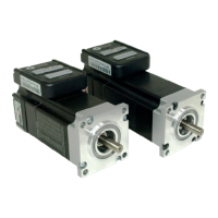
Alarm, In-position Output
The outputs are isolated and you can take them as electronic switch. An upper resistor needs to be
used to limit the current. Its resistance is depending on the input current requirement of the
controller. The supply voltage for those outputs can also be 24V. The resistor R is depending on the
input current of the controller.
ALM+
ALM-
Alarm
Controller
5V
PED+
PED-
In-Position
Control Signal
Connector
R
R
iSV-x23xxx
Alarm, in-position signal connection of ES-DXXX
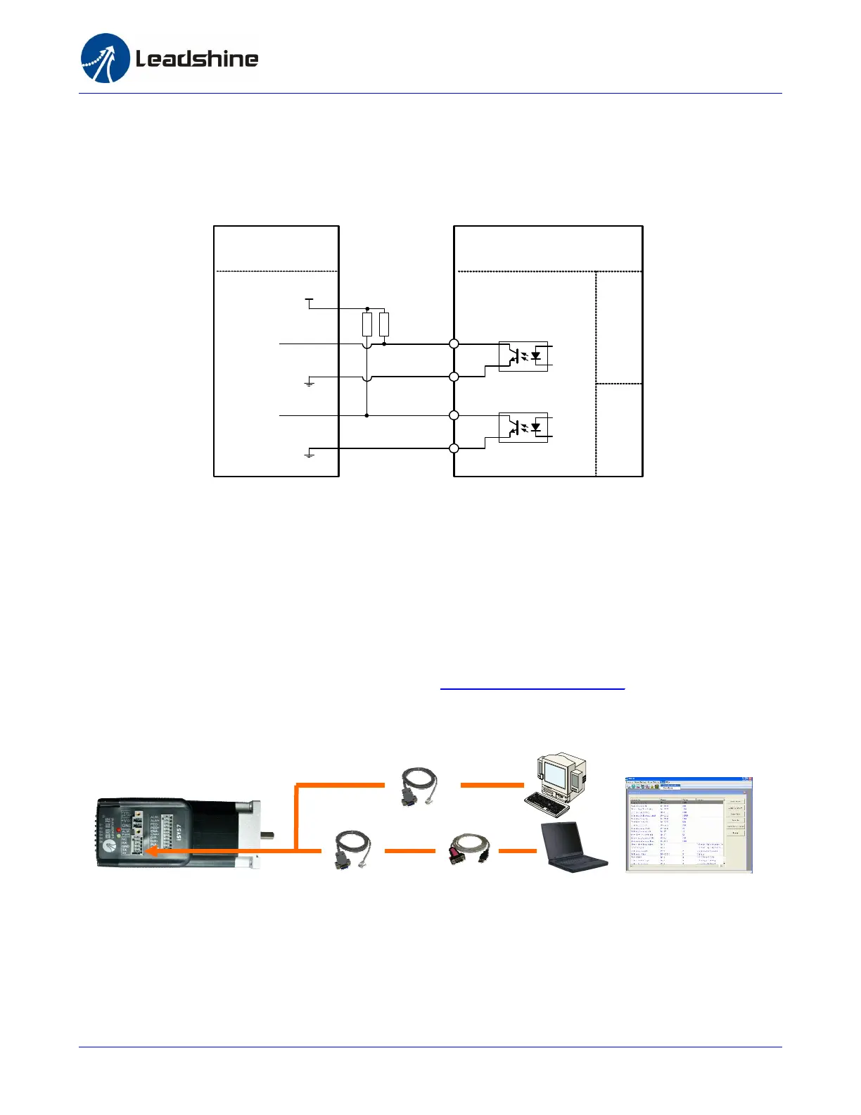
Connecting PC
A RS232 communication port is built into the integrated servo drive for communication and
configuration. Connect this port to the PC’s serial port. Then you can turn the motor in PC software.
This software - ProTuner, is designed to configure the integrated servo drive. You can configure the
control mode, step resolution, current rate and active level of inputs/outputs in ProTuner.
The ProTuner can be downloaded from our website: http://www.leadshine.com or you may also get it
from Leadshine CD. It is recommended to get it from the website because it is always the latest.
Install it on your PC and make it ready for use later.
Connect iSV-23130 to PC
A RS232 cable is needed for the communication between the drive’s RS232 port and the PC’s serial
port. It will be shipped with the kit if you include it in the order. It is also possible to make this cable
yourself. One end of this cable is a 5-pin plug-in terminal block and the other end of cable is a 9 pin
D-Sub female connector. If your PC does not have a serial port, a USB-to-Serial converter which
simulates the serial port is required. The power should be turned off when you perform any
Or
RS232 Cable
USB-232 Converter
ProTuner
 Loading...