Hardware installation manual of the integrated servo motor
2
Getting Start
To get start you need one integrated servo motor, one DC power supply and one motion controller.
The motion controller such as indexer, pulse generator or PLC is only required when you need to
rotate the motor. If you have a PC with one serial port or USB-RS232 converter, you can also rotate
the motor in the PC software. However it is recommended to verify the complete function of the
integrated easy servo using a motion controller.
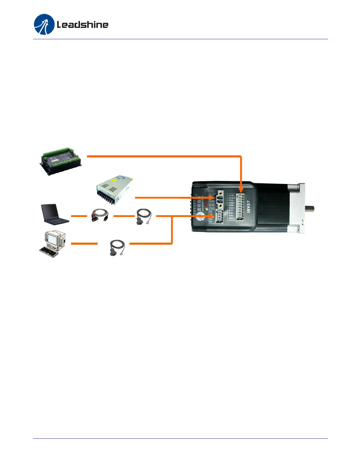
Wiring Diagrams
Wiring Diagram of integrated servo iSV-B23xxx
Connecting Power Supply
The ISV-B23XXX accepts DC power input. The power connections are only the positive and negative
wires. However you need to pay attention to wire polarity. A 2-pin pluggable screw connector is used
for power supply connection. Looking at the drive front you should find the printed “+Vdc” and
“GND” symbol. Connect the positive wire to “+Vdc” terminal and connect the negative wire to “GND”
terminal. Note that the power should be switch off when you make the connections. Note: Do not
exceed the input voltage range of the iSV motor. Please consult Power Supply Selection chapter in
the manual for the recommended supply voltage.
RS232 Cable
Or USB-232 Converter
Motion Controller
Power Supply
 Loading...