5
5
4
4
3
3
2
2
1
1
D D
C C
B B
A A
Title
Size Document Number Rev
Date: Sheet
of
DWGW PSX 003 4
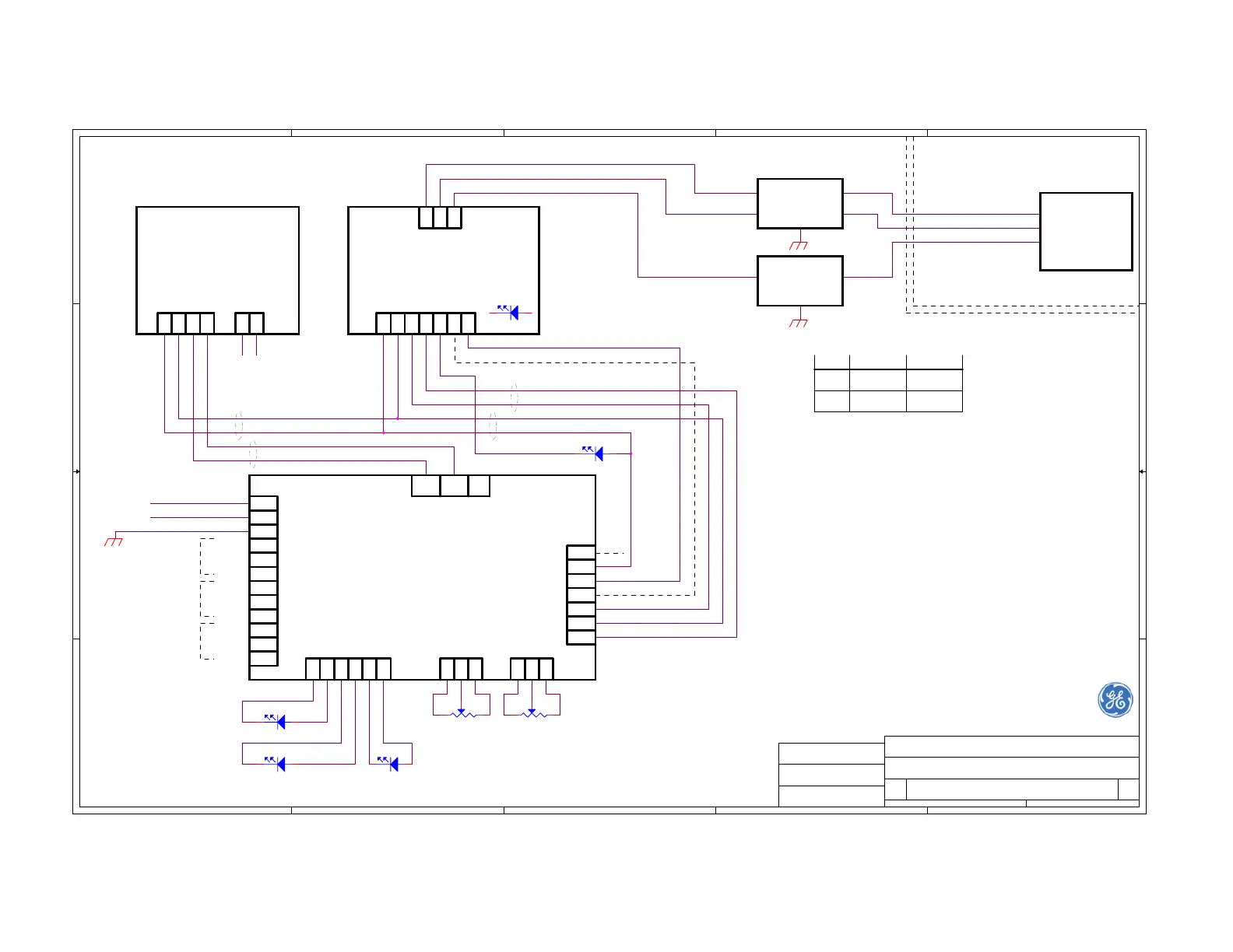
PS-220 Rev. D1 Wiring Diagram for 110 / 220VAC
Ionics Agar Environmental Ltd.
B
11Monday, March 03, 2008
GE Analytical Instruments
1
2
3
4
5
6
7
8
9
10
11
12
N(-)
L(+)
GND
ACOM
ANC
ANO
WCOM
WNC
WNO
FCOM
FNC
FNO
123456
TB9
TB2
W- W+
O- O+ A- A+
12
TB7
3 12
TB8
3
1
2
3
4
5
6
TB1
+12V
GND
SIG.
Fail on RY2
Fail Relay RY3
+15V
WATER
LIGHT
OIL
LIGHT
AIR /
HIGH OIL
LIGHT
OIL / AIR
RELAY (RY2)
WATER / OIL
RELAY (RY1)
FAIL
RELAY (RY3)
NULL
PHASE
EARTH
AC Power
Input
PS-220 Rev. D1 Main Board
DWGS PSX 012 1
*
13
*
13
GAIN
OIL / AIR
SETTING
1234
TB5
567
123
TB6
24 11 2 3
TB4TB3
Built in Test Board
DWGS PSX 004 3 Rev. A
4-20mA Output &
Bar-Graph Display Board
DWGS PSX 005 2
Optional (/420 or /420/BG)
Q11-CTP4
+-
4-20 mA Output
RED
BLACK
YELLOW
RED
BLUE
YELLOW
WHITE
RED
NOTE ON INTERNAL WIRING
FAIL LIGHT
POWER ON
DRAWING BY:
CHECKED BY:
APPROVED BY:
S. DAVID
S. DAVID
S. DAVID
ID-220 Series
Oil-on-Water
Detector
Hazardous Area
DET SIGNAL (Iout)
DET - (GND)
13
42
Safety
Barrier
#1
13
DET +
DET +
DET - (GND)
DET SIGNAL (Iout)
Sensor
Input
Optional (/CEN)
Safety
Barrier
#2
Recommended Safety Barriers:
Vendor Barrier #1 Barrier #2
MTL
MTL
715+ 710+
7715+ 7710+
Notes for Safety Barriers:
1. Terminal numbers shown are for MTL Barriers.
2. Barriers should be earthed by a 4 sq. mm (minimum) wire .
Notes for field wiring:
1. Refer to drawing DWGV 220 001 2 for additional information.
2. Field cable should have 3 untwisted stranded wires.
3. Capacitance between each two wires: 200 pF/m maximum.
4. Inductance of each wire: 0.7 uH/m maximum.
5. Cable insulation should withstand an AC test voltage
of 500 V R.M.S. to earth or to apparatus frame for one minute.
3. Safety Barriers are installed in Safe Area.
4. Refer to drawing DWGV 220 001 2 for additional information.
1. The Board is configured to 110VAC OR 220VAC by soldered jumpers.
2. R2 (10K trimmer) may be installed off board next to Air / High Oil Light on front panel.
3. R5 (10K trimmer) may be installed off board next to Water Light on front panel.
4. Alternatively, R2 and R5 may be installed on board.
Notes for Main Board:
Note on internal wiring:
The wire from TB1-4 is not usually connected. It may be used for
backward compatibility with systems that used to
indicate failure by de-energizing relay RY2.
7
TP3
123
TB10
RED LED YELLOW LED
R5 10K
RED LED
R2 10K
GREEN LED
GREEN LED x3