• Pull the Sensor Assembly out of the liquid.
AIR / HIGH OIL light should stay on.
5.1.5 Calibration Check
Check the system for proper detection of Water, Air, Water/Oil Interface,
and Second Alarm Point (as described just above, except additional
adjustments).
5.2 Built-in Test
5.2.1 TEST Button
The TEST button is located:
For the /N4 option - on a TEST board inside the enclosure;
For the /N7 and other enclosure options - on the front panel / under the window.
BEWARE OF HIGH VOLTAGE 110 or 220V INSIDE ENCLOSURE!
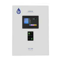
To check the PS-220, push TEST button for a few seconds, then release.
The PS-220 will receive a ramping test signal instead of real sensor signal, and
the indicating lights will turn on consecutively: AIR / HIGH OIL, OIL, then WATER.
For the Bar-Graph and/or 4-20mA options, appropriate outputs should also react
in a compatible manner.
5.2.2 FAIL / DETECTOR DISCONNECTED Indicator
This light is located on the front panel of PS-220.
The light indicates, when turned on, that at least one of the three wires coming
from the Sensor is disconnected, or that Sensor signal is abnormal, or that the
optional Safety Barriers has an open circuit (burnt internal fuse).
If this indication is on, refer to Section 6 (PROBLEMS AND SOLUTIONS).
Relay RY3 is a Fail relay that works together with the Fail indicator. If everything
is normal, the relay will be energized. If the sensor fails or power is interrupted, the
relay will be de-energized (fail safe operation). The contacts are available at TB2
(see drawing DWGS PSX 004 4).



 To Next Page