1. System Description
LEAKWISE
®
system provides oil sheen detection and indication of oil layer thickness. A typical
application is valve/pump control for an oil separator draining.
The system consists of two main parts:
A. A single Sensor, model ID-221 / ID-223/ ID-225 / ID-227.
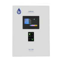
B. PS-220 Analog Signal Processor / Controller for supporting a single sensor.
The Sensor Assembly consists of a Floating Sensor complete with electrical cable that connects
to the PS-220.
The PS-220 signal processor is housed in a NEMA 4 (IP65) weather-proof or NEMA 7 or Exd Ex-
proof enclosure, and powered by either 110 VAC or 220 VAC or 24 VDC or 12 VDC, at choice.
The system may also be solar powered.
The Signal Processor converts supplied power into a stable 12 volts DC that feeds the Sensor.
For ATEX approved applications, optional Zener Safety Barriers are used between Signal
Processor and sensor. (Refer to Section 9 - Installation in Hazardous Area).
The antenna of Floating Sensor detects the signal difference between Air (no liquid), Oil, and
Water. The Sensor transmits a raw current, proportional to this difference, to the Signal
Processor.
The raw signal received from the sensor is amplified and filtered, and then used to activate status
lights, relay outputs (dry contacts), and an optional 4-20mA current output.
Adjusting the relays trip thresholds provides detection points of "WATER", "OIL", and "AIR / HIGH
OIL".
The Floating Sensor floats on water surface in the well, sump or tank. Refer to the specific sensor
User Guide for additional information and guidance.
An optional 4-20mA output is used to produce a current equivalent to sensor signal, ranging from
4mA in WATER to 20mA in AIR. When an OIL layer on WATER is detected, the current
increases above 4mA, and a thicker OIL layer produces an increase of this current toward 20mA.
In maximal oil layer the output current will be about 18mA. This output can be routed through the
contacts of the Fail relay, to cut the current to 0 mA during a failure.
To look through the PS-220 options, refer to Section 8 (Appendix A).
Local indicating lights on the front panel of the enclosure show current status of the Sensor in the
well/sump/tank:
AIR / HIGH OIL (yellow light), OIL (red light), WATER (green light).
A red FAIL light is an additional indication on the front panel in case of a failure.
Another option is a Bar-Graph display, which visually indicates changes in oil layer thickness.