5
5
4
4
3
3
2
2
1
1
D D
C C
B B
A A
Title
Size Document Number Rev
Date: Sheet
of
DWGS PSX 004 4 0
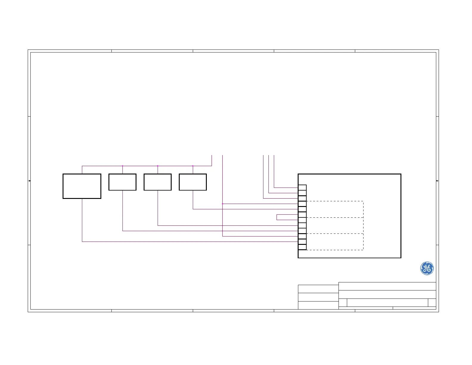
PS-220 Rev.D: Wiring Diagram of Relay Outputs
Ionics Agar Environmental Ltd.
B
11Sunday, November 18, 2007
GE Analytical Instruments
S. DAVID
S. DAVID
CHECKED BY:
APPROVED BY:
DRAWING BY:
S. DAVID
1
2
3
4
5
6
7
8
9
10
11
12
PS-220 Rev. D1 Main Board
RY2
OIL / AIR RELAY
RY1
WATER / OIL RELAY
RY3
FAIL RELAY
N (-)
L (+)
GND
ACOM
ANC
ANO
WCOM
WNC
WNO
FCOM
FNC
FNO
PS-220
Power
Input
L (+)
TB2
LOAD #3LOAD #2LOAD #1
N (-)
Loads
Power
Input
FAIL
INDICATION
(Fail Safe)
This connection is applicable for ID-221, ID-223, ID-225 and ID-227 sensors.
A load can be an audio alarm, a valve or a power relay connected to a pump.
LOAD #1 will be activated whenever WATER light is on.
LOAD #2 will be activated whenever OIL light is on.
LOAD #3 will be activated whenever AIR/HIGH OIL light is on.
Relays RY1 & RY2 have "dry" contacts rated 4 Amp. at 30VDC and 250VAC. RY3 is rated 3 Amp.
Loads power input can be the same as PS-220 power input or different.
Notes for LOAD #2 with ID-223:
LOAD #2 can be activated temporarily (for less than a second) even without presense of oil when:
1. Sensor starts floating on rising water, or
2. Sensor stops floating as water level decreases, or
3. Sensor floates in turbulent conditions.
If this raises a problem in some applications then:
1. If the load is connected to a computerized system, add a 2 seconds delay by software.
2. Otherwise, connect the load through a "time delay relay" that operates in a
"delay on operate" mode with a 2 seconds delay.
3. Use the delay option on PS-220 Main Board (JP1 and JP2).
FAIL indication will be activated whenever FAIL light is off or PS-220 power is interrupted.