PRIMARY FLIGHT
CONTROLS
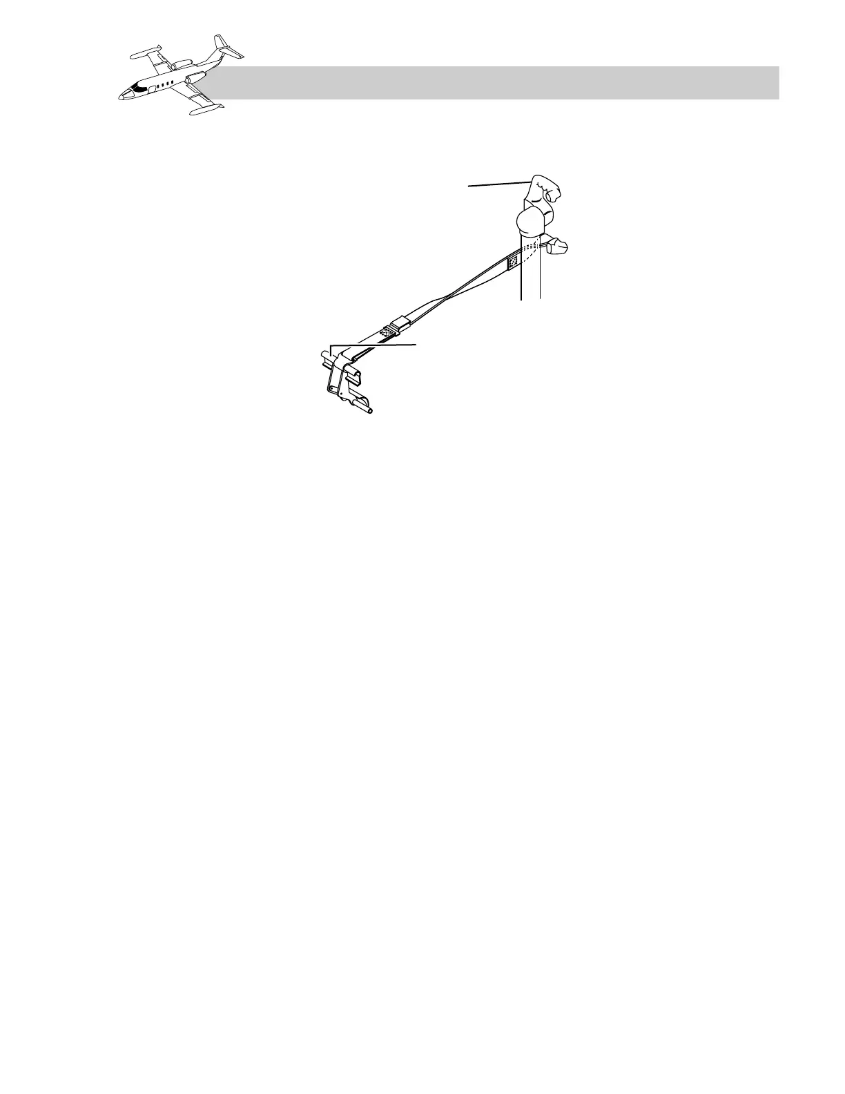
ELEVATORS
The elevators are hinged to the aft edge of the
horizontal stabilizer and are positioned by fore-
and-aft movement of the control column. Three
scuppers are located near the aft edge of each
elevator for moisture drainage, and static dis-
charge wicks are attached to the trailing edge of
each elevator.
The elevators can also be positioned through an
electrically actuated pitch servo.
On SNs 24-139 and subsequent, all model 25
airplanes, and airplanes modified for 45,000-foot
operation, a bob weight attached to the control
column and a downspring assembly in the eleva-
tor control linkage are incorporated to enhance
pitch stability. Airplanes prior to SNs 24-139
have an elevator downspring located in the aft
tailcone but do not have a bob weight.
Figure 15-3 shows the elevator control system.
Pitch Servo
The pitch servo (torquer) is DC operated. It is
mechanically connected to the elevator control
linkage through a capstan mechanism incorpo-
rating an electric clutch and a mechanical slip
clutch. Three flight control systems use the pitch
servo to operate the elevators:
• Autopilot—When engaged, the autopilot
can alter noseup or nosedown attitude by
commanding the servo to position the ele-
vator up or down, as required.
• Stall warning systems—When engaged,
either system can cause the servo to posi-
tion the elevator to decrease the angle of
attack in the event of an impending stall
(stick pusher).
• Nudger—On airplanes with a two-speed
trim system, the stick pusher applies a
pusher force in conjunction with shaker
actuation.
• Stick puller (all airplanes except model
23)—Operating through the L STALL
WARNING switch, the system can com-
mand the servo to position the elevator for
noseup.