77
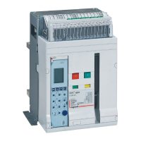
DMX
3
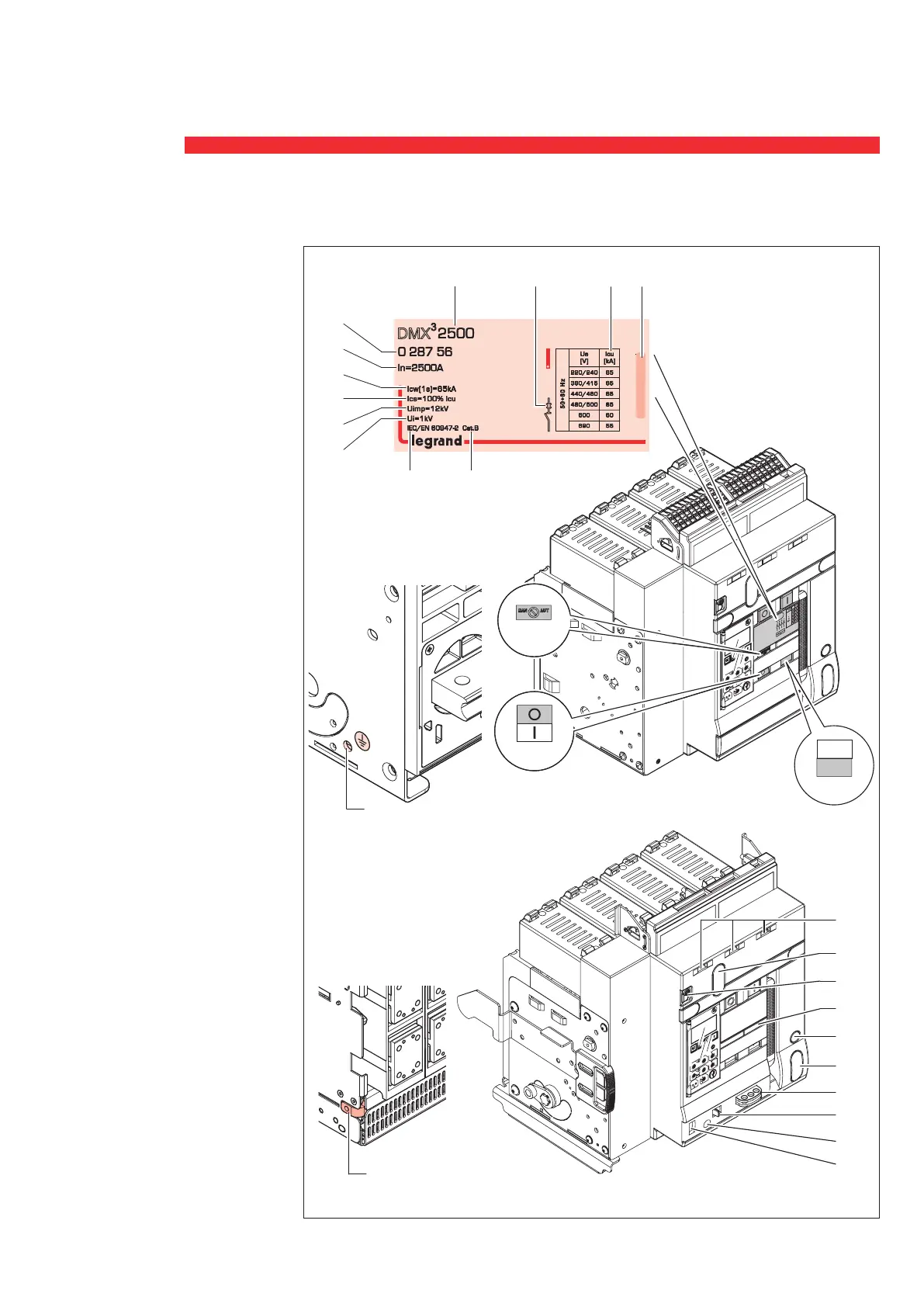
1 Main contacts status indication
2 Spring status indication
3 Reset button for tripping device
4a Product
reference
4b Product type
4c Utilization Category
4d Standards
compliance
4e Rated service short-circuit breaking
capacity
4f Rated short-time withstand
current
4g Rated Current
4h Rated insulation voltage
4i Rated impulse withstand voltage
4j Coloured label for breaking capacity
4k Identification symbol of the device
4l Rated ultimate short-circuit breaking
capacity according to the rated
operational voltage Ue
5 Visualization windows for electrical
auxiliares
6 Place for key lock or padlock
in open position
7 Place for operation counter
8 Place to lay draw-out Bar
9 Place for key lock in in draw-out
and test position
10 Pad Lock of draw-out window
11 Racking shutter: Bring to the right
in order packing to insert the draw-
out bar (operation disabled if the
breaker is closed)
12 Draw-out Bar insertion
13 Draw-out position indication:
inserted/test/draw-out
14 Dielectric test selector
(if present)
15 Earth connection
4. Identification
discharged
10
5
2
0
.7
0.4
5
0
.
6
0
.5
I
r
2
0.9
8
0.8
10
xI
r
3
Im
6
4
5
s
xIn
0
.
1
0.0
0
.0
1
2
0
5
10
@6I
r
30
tr
30
2
0
0.
3
tm
0.2
0.3 0.2
0
.
1
I
>
1.0
5
I
>
.90
xIr
ON
N
0.00
0
.02
0.04
0.06
0.0
8
0.1
I
2
t
=k
@
1
2I
r
MEM
=OF
F
s
1
.
.
5
I
i
I
cw
4
3
2
8
6
10
12
15
xIn
charged
discharged
2
3
1
1
0
5
2
0.7
0
.
4
5
0.6
0
.
5
Ir
2
0
.
9
8
0
.
8
1
0
xI
r
3
I
m
6
4
5
s
xI
n
0
.1
0
.0
0.
01
2
0
5
1
0
@
6
I
r
30
tr
30
20
0
.3
tm
0.2
0
.3
0
.2
0
.1
I
>1.
05
I
>.90
x
I
r
ON
N
0
.0
0
0
.0
2
0
.0
4
0.0
6
0
.08
0
.1
I
2
t=
k
@
1
2
I
r
ME
M
=OFF
s
1
.
.
5
I
i
Icw
4
3
2
8
6
1
0
1
2
1
5
xI
n
8
10
11
12
13
9
7
14
6
5
15
15
4i
4h
4f
4e
4a
4b
4j
4l
4d
4k
4c
4g
Fixed version
Draw-out version
 Loading...