
M
Mallory MeyersAug 13, 2025
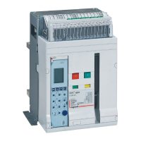
What to do if LEGRAND Circuit breakers racking shutter does not re-close automatically?
- VValerie RogersAug 13, 2025
If the LEGRAND Circuit breakers racking shutter doesn't re-close automatically after the racking handle is pulled out, it might be because the breaker is in-between the Service/Test/Isolated position. Ensure the position indicator is aligned with one of the distinct positions by racking the breaker in or out.