Do you have a question about the LEGRAND DPX3 and is the answer not in the manual?
Identifies the main test button for differential current.
Indicates the device status through visual signals.
Used for navigating through menus or settings.
Allows adjustment of device parameters.
Step-by-step guide for inserting batteries into the device.
Guidelines for environmentally sound disposal of used batteries.
Lists the factory default configuration values for parameters.
Explains how to set differential current and time delay parameters.
Describes how to view current settings on the device.
How I∆n and t values alternate on the display frequency.
Indicates the display when the device has low battery power.
Shows measured IN, I∆, and last intervention values.
Describes normal operation and blocked states.
Explains the position for dielectric testing.
Overview of testing installation insulation.
Method to disconnect the internal electronic circuit.
Detailed wiring for dielectric tests with voltage and resistance limits.
Step-by-step procedure for insulation testing.
Step-by-step procedure for isolating the internal circuit.
Explains external power, differential block, and direct power connections.
Details the connection for dielectric testing.
Shows the internal wiring diagram of the device.
Shows tripping times for instantaneous setting.
Displays tripping times for 0.3s, 1s, and 3s delay settings.
| Brand | LEGRAND |
|---|---|
| Category | Circuit breakers |
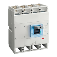
| Number of Poles | 3P, 4P |
| Standards | IEC 60947-2 |
| Mechanical Durability | 20000 cycles |
| Terminal Type | Screw Terminals |
| Protection Degree | IP20 |
| Storage Temperature | -40°C to +85°C |