EasyManua.ls Logo

LEGRAND DPX User Manual

LEGRAND DPX
20 pages
To Next Page IconTo Next Page
Page #1 background imageLoading...
Page #1 background image
Notice de montage
Instruction sheet
Anweisungen
Hoja de instrucciones
Foglio istruzioni
Folha de instruções
Bycnherwbb
Instrukcje montażu
Bilgi broflürü
02/2009-01 GF
Y3466A
®
Disjoncteurs débrochables
Draw-out circuit breakers
Herausnehmbare Selbstschalter
Interruptores automáticos extraíbles
Interruttori automatici estraibili
Disjuntores extraíveis
C]tvyst fdnjvfnbxtcrbt
dsrk.xfntkb
Wyłączniki samoczynne wysuwane
Çekmeli otomatik devre kesici anahtarlar
DPX 1250 - DPX 1600 - DPX-I 1600
DPX
Question and Answer IconNeed help?

Do you have a question about the LEGRAND DPX and is the answer not in the manual?

LEGRAND DPX Specifications

General IconGeneral
BrandLEGRAND
ModelDPX
CategoryCircuit breakers
LanguageEnglish

Summary

Circuit Breaker Assembly Steps

Terminal, Barrier, and Protection Installation

Installing rear terminals, interphase barriers, and protection 'V'.

Key Lock and Signalling Contact Mounting

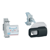
Mounting optional key lock and signalling contact.

Base Fixing and Securement

Fixing the base and securing it to its support.

Mounting Breaker Transformation Components

Mounting of terminals, protections, base, and other components.

Auxiliary Connector Wiring Transformation

Moving electronic circuit wirings to rear connectors.

Diaphragm Placement and Breaker Mounting

Placing diaphragms and mounting breaker on plate.

Steel Plate Fixing

Securing the steel plate to the circuit breaker.

Terminal Bridge and Logic Selectivity

Connecting terminals X5-X6 and setting logic selectivity.

Front Cover and Lock Assembly

Dismounting front cover and assembling locks.

Toggle Extension and Shield Mounting

Mounting toggle extension and terminal shields.

Crank Operation and Breaker Insertion

Checking crank operation and inserting breaker into base.

Circuit Breaker Positions and Extraction

Operational Positions (Plugged, Test, Isolated)

Indicates circuit breaker positions via signal colors.

Circuit Breaker Extraction from Base

Procedure for removing the circuit breaker from its base.

Auxiliary Circuit Wiring

IC, IIC, IIIC Connection Types

Wiring details for IC, IIC, and IIIC auxiliary circuit types.

S, M, T Connection Types and Functions

Wiring details for S, M, T auxiliary circuits and functions.

Trip and Motor Functions

Description of shunt trip, undervoltage, and motor functions.

Panel Specifications and Operation Modes

Front Panel Cut-out

Specifications for cutting the front panel for direct toggle versions.

Rotary Handle Operation

Information regarding operation with a rotary handle.

Motor Operator Operation

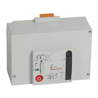
Information regarding operation with a motor operator.

Detachable Chassis Connection

Terminal Support and Cable Fixing

Terminals for electrical connections only; cables must be secured.

Related product manuals