Do you have a question about the LEGRAND DX3 Series and is the answer not in the manual?
Lists catalog numbers (4063 14, 15, 16) corresponding to 2, 3, and 4 pole/module devices.
Details fixing on symmetric rail EN/IEC 60715 or DIN 35 rail, and available operating positions.
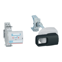
Describes how to clip the Manual Supply Invertor (MSI) between two modular protection devices.
Step-by-step guide on how to perform source inversion using the device handle and slider.
Illustrates compatible device associations and module widths for the MSI.
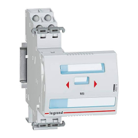
Details the markings present on the front face of the MSI, including name, arrows, and logo.
Specifies the IP40 protection index and resistance to sinusoidal vibrations per IEC 60068-2-6.
Describes the 10% glass fiber reinforced polycarbonate material, including heat and fire resistance.
Provides average weight per device and volume when packed for different catalog numbers.
Specifies the operating and storage temperature ranges for the device.
Lists compliance with CEE guidelines and IEC/EN 60947-1 for circuit breaker usage.
Covers halogen-free plastic materials and packaging regulations according to ISO and EU directives.
The Legrand DX³ Manual Supply Invertor (MSI) is a device designed to allow an end-user to manually switch between two different power sources, such as the main supply and a generator, in the event of a power outage. This functionality is crucial for maintaining power to a pre-defined circuit when the primary source is unavailable.
The MSI facilitates the manual inversion of a power source. When the main supply fails, the user can operate the MSI to switch to an alternative power source, like a generator. The operation involves a simple three-step process:
The device is designed to be installed between two modular protection devices, ensuring a secure and integrated solution for power management. It is clipped onto the associated device using plastic clamps located on each side of the MSI, allowing for both right-side and left-side assembly.
The DX³ Manual Supply Invertor is available in three different models, each designed for a specific number of poles and modules:
The device has a consistent height of 83.4 mm and a depth of 76.7 mm. The width varies depending on the model:
The MSI is constructed from 10% glass fiber reinforced polycarbonate. This material is self-extinguishing, heat and fire resistant, meeting the EN 60898-1 standard with a glow-wire test at 960°C. All plastic materials are halogen-free, and parts are marked according to ISO 11469 and ISO 1043.
The device boasts an IP40 protection index, safeguarding against solid bodies larger than 1 mm and offering no specific protection against liquids, in accordance with IEC 529, EN 60529, and NF C 20-010 standards.
Power Dissipated: 0 W.
The DX³ Manual Supply Invertor complies with CEE guidelines (73/23/CEE + 93/68/CEE). Legrand devices are designed for use under conditions defined by IEC/EN 60947-1. The performance of circuit breakers can be affected by specific climates such as hot dry, cold dry, hot humid, and salt fog atmospheres. Packaging design and manufacture adhere to decree 98-638 of 07.20.98 and Directive 94/62/EC.
Fixing: The MSI is designed for easy installation on a symmetric rail EN/IEC 60715 or DIN 35 rail, utilizing the associated device for mounting. No tools are required for fixing the MSI and protection devices, or for mounting on the DIN rail.
Operating Positions: The device can be installed in various orientations, including vertical, horizontal, upside down, or on its side, offering flexibility in installation.
Identification: The MSI is equipped with multiple windows, ensuring that all information from the associated device remains visible. The front face features permanent ink pad printing, displaying the device name (MSI), directional arrows, Legrand reference code and logo, and the Legrand mark. It also includes a label holder for additional identification and handle marking.
Lockout: The MSI incorporates security seals to ensure the integrity of the association between the MSI and its connected device. These seals can be removed using a flat screwdriver (5.5 mm, maximum 6 mm). For enhanced security, the associated device can be locked out using a padlock (Cat. Nos 4 063 13 or 227 97) and a padlock support (Cat. No 4 063 03) on the powered-on device (MCB or IS).
Association Table: To ensure proper functionality, the Manual Supply Invertor must be installed with the same type of devices (IS-IS or MCB-MCB) on both its left and right sides. This ensures compatibility and reliable operation within the circuit.