2
BACKFEED
PROTECTION
x3
MAINS INPUT
INGRESSO RETE
OUTPUT (TO LOADS)
USCITA
EXTERNAL BATTERY
CABINET BATTERY ESTERNO
BACKFEED
PROTECTION
x3
MAINS INPUT
INGRESSO RETE
OUTPUT (TO LOADS)
USCITA
EXTERNAL BATTERY
CABINET BATTERY ESTERNO
Fig. 1
Fig. 3
Fig. 2
Fig. 4
This attachment is addressed only to specialized technicians (see
par. 2.2.1 of the installation manual).
It does not replace the installation manual that must be carefully read.
The specialized technican should not leave this attachment and the instal-
lation manual available to the operator.
Sections 1 and 2 provide the conguration instructions.
Sections 3 and 4 provide the start-up instructions.
Section 5 provides solutions to the most common anomalies that could be
found during the rst start-up.
Neutral and earth are always necessary for powering the Trimod
HE® UPS.
SECTION 1 FACTORY CONFIGURATION
Three-phase input/three-phase output conguration
To use Trimod HE® in the THREE PHASE IN/THREE PHASE OUT CONFIGURATION
WITH INPUT BYPASS IN COMMON, simply connect it to the electrical system.
See installation manual, paragraph 4.3.1. Check also cable section and protec-
tion sizing. See installation manual, chapter 10.
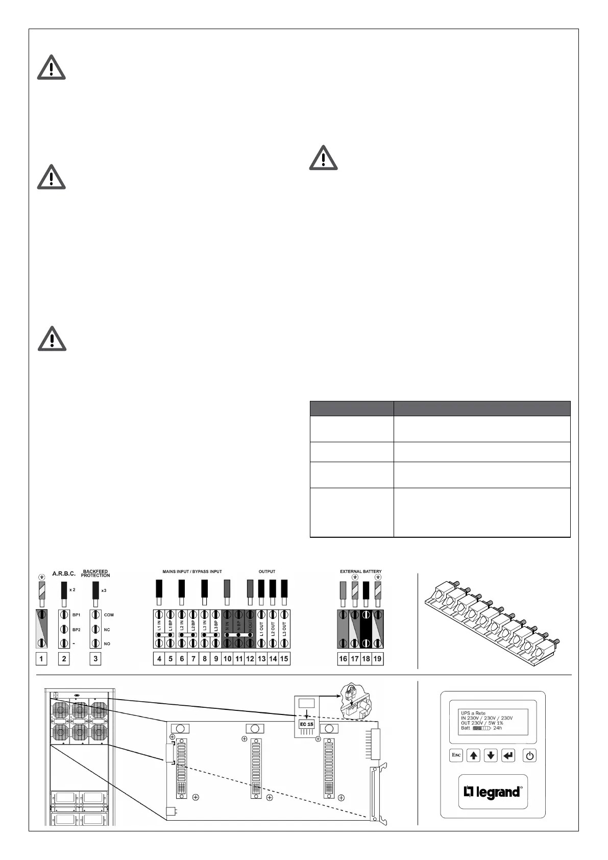
SECTION 2 – CHANGING THE FACTORY CONFIGURATION
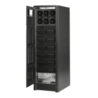
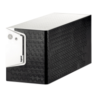
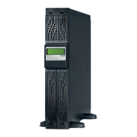
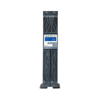
If the factory conguration has to be changed, operate on the distribution
terminal block (Fig. 1) by means of the jumpers (Fig. 2) on the backplane
boards (Fig. 3) and on the control panel (Fig. 4) as explained in the following
paragraphs.
Congure the UPS before connecting Trimod HE® to the electrical
system and to the external battery cabinets if installed. Open all
the UPS battery breakers, if installed. Make sure there are no dan-
gerous voltages on the terminal block.
2.1 - Three-phase input and output conguration with input bypass
separated
• Adjust the distribution terminal block. See installation manual,
paragraph 4.3.2
• Check cable section and protection sizing. See installation manual, chapter 10.
2.2 – Three-phase input and single-phase output conguration
• Adjust the distribution terminal block. See installation manual,
paragraph 4.3.3.
• Plug in EC15 connectors. See installation manual, paragraph 4.3.3.
• Set the single-phase inverter via the control panel. See installation manual,
paragraph 5.5.
• Check cable section and protection sizing. See installation manual,
chapter 10.
2.3 – Single-phase output and input conguration
• Adjust the distribution terminal block. See installation manual, paragraph 4.3.4.
• Help Trimod HE® conguration
• Plug in EC15 connectors. See installation manual, paragraph 4.3.4.
• Set the single-phase inverter via the control panel.
See installation manual, paragraph 5.5.
• Check cable section and protection sizing. See installation manual, chapter 10.
2.4 – Single-phase input and three-phase output 120° conguration
• Adjust the distribution terminal block. See installation manual, paragraph 4.3.5.
• Set the 120° three-phase inverter via the control panel. See installation manu-
al, paragraph 5.5.
• Check cable section and protection sizing. See installation manual, chapter 10.
The Trimod HE® bypass is not available in this conguration. Nev-
er close the S1 maintenance bypass switch and the S5 input by-
pass switch.
2.5 - Separate three-phase output and single-phase input conguration
• Adjust the distribution terminal block. See installation manual, paragraph 4.3.6.
• Set the separate three-phase inverter via the control panel. See installation
manual, paragraph 5.5.
• Check cable section and protection sizing. See installation manual, chapter 10.
SECTION 3 PRELIMINARY STARTUP OPERATIONS
Carry out the operations with the switches S1, S2, S3 and S5 open (OFF position).
• Check voltage between neutral and earth (about 0V).
• Check voltage on the input terminal block according to the conguration chosen.
• Check battery voltage +BATT / -BATT (about 250V).
SECTION 4 STARTUP OPERATIONS
The UPS can now be powered and start-up can be done. See installation man-
ual, paragraph 5.5.
• Check that the voltage and output frequency set are those required by the load.
• Close the S3 mains switch, the S5 input bypass and the S2 output discon-
nector switch (ON position) to power the electrical line downstream of the
Trimod HE®.
• The S1 maintenance bypass switch must remain open (OFF position).
SECTION 5 ANOMALIES IN THE FIRST STARTUP PHASE
INDICATION MEANING AND SOLUTION
Three Phase Voltage
Sequence Invalid!
The sequence of the input phases is not correct.
Reverse two phases.
START-UP Error! Check if all battery fuses are present.
Mains not Present!
Start-up not Allowed
No input mains.
Check if the input is powered.
Emergency Power Off
turn-OFF
UPS shut down due to an Emergency Power Off.
Check if the jumper is on the EPO contact.
If an emergency button has been connected, check
that the normally closed contact (NC) has been used.
 Loading...