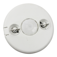
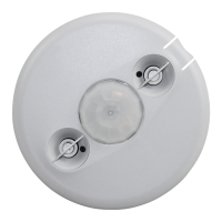
DT-305
360º Dual Technology Low
Voltage Occupancy Sensor
Ceiling Mount
Quick Start Guide
THIS UNIT IS PRESET FOR BASIC
OPERATION AS DESCRIBED IN THIS
GUIDE. ADJUSTMENT IS OPTIONAL.
For full operational details, adjustment and
more features of the product, see the Installation
Instructions at www.wattstopper.com
Installation shall be in accordance with all
applicable regulations, and codes.
SENSOR PLACEMENT 10’ MAX. HEIGHT
MOUNTING
WARNING
TURN POWER OFF AT CIRCUIT BREAKER
BEFORE INSTALLING POWER PACKS.
Load #1
Load #2
(Optional)
DT-305
Standard wiring with local off switch
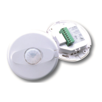
Rear Housing
Depluggable
Terminal
Front Cover
Ceiling
Spring Clips (2)
Blue
Control Out
+24V
Common
Low Voltage
Class 2
Line
Voltage
Line
Neutral
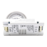
Feed Through
Power Pack
Black
Red
#1 #2
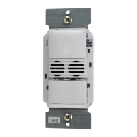
Line Voltage
Switches
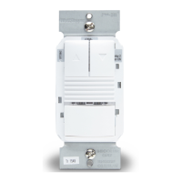
LVS-1
Load
Rear Housing
Depluggable
Terminal
Front Cover
Ceiling
Spring Clips (2)
Blue
Control Out
Black
+24V
Low Voltage
Class 2
Line Voltage
Line
Neutral
Feed Through
Power Pack
Man.Switch
Red
DT-305
Manual-On wiring with low voltage momentary switch
Common
For low voltage
momentary switch set
DT-305 DIP switches:
1 = Off
2 = On
3 = On
Man.Switch
Common
Jumper
Back
of
LVS-1
CONNECTING WIRES
• Care should be taken to separate high voltage power from low voltage (Class 2) control wiring.
• All connections to sensor are low voltage, Class 2.
Rear
housing
Depluggable
terminal
4" Octagonal J-Box
(at least 1.5" deep)
Front
cover
Ceiling
Screws
To octagon box:
Rear
housing
Depluggable terminal
Front
cover
Ceiling
Spring clips (2)
Through ceiling tile:
Sensor
28'
30'
Sensor
Pendant xtures
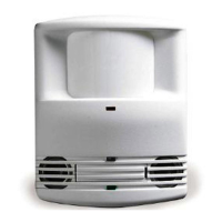
Do NOT mount a ceiling sensor above a suspended
fixture. Use a ceiling/wall mount sensor mounted to
the wall below the plane of the bottom of the fixture.
Hot air supply
6’
Sensor
Mount sensor at least 6’ away from hot air supply
White
Black
Red
Line Voltage
Wire Color Legend