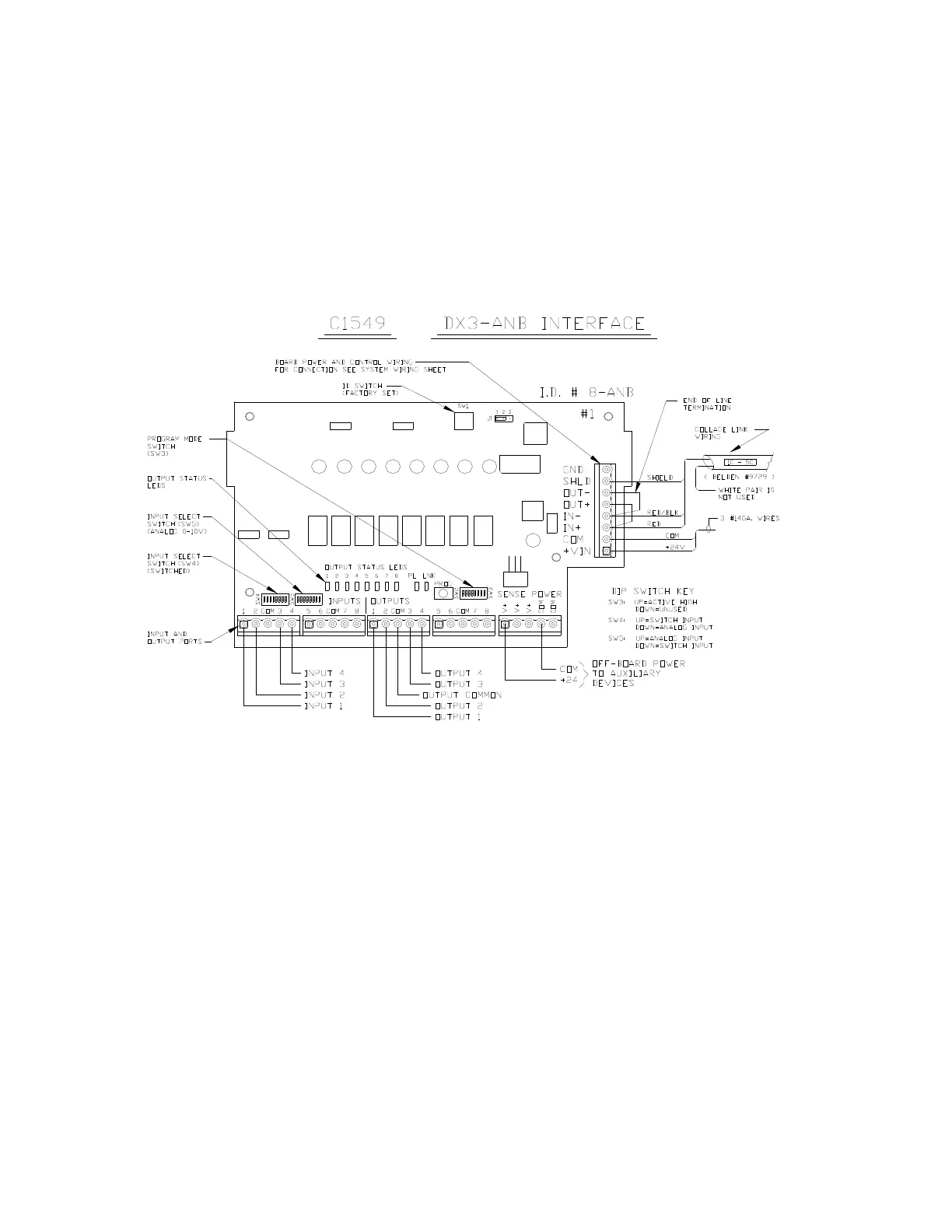
9.3 Analog Input Control Board (P/N C1549)
The Analog Input Control Board provides up to (8) inputs for a 0-9.0vdc analog signal. This can be
from an auxiliary analog device or from a switch contact. The applicable dimmers must be
programmed to respond to these analog control signals. Switched inputs can also activate the system
Panics or Take Controls, and the outputs can be set up to light panic indicators. Only active high inputs
are allowed, with a maximum input voltage of 9.0vdc. Three boards are allowed in a system, addressed
via the SW1 rotary ID switch. The boards are wired on one of the Collage control links from TB2, 3,
or 4. Figure 23 illustrates the wiring of the board. The DIP switches are factory set for the particular
function required by the project and should not be changed unless directed by the factory.
Figure 23: Analog Control Board
DX3 Manual 37