2 System Design and Layout
2.1 Typical System Riser
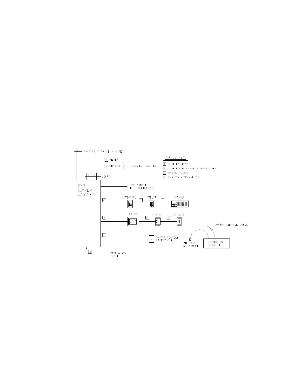
Figure 2 illustrates a typical system riser incorporating a theatrical console, architectural controls and
controllable fixtures. While Figure 2 illustrates a single rack at 120/208vac, multiple racks can be
linked together with some racks on 120v and some racks on 277v. This allows for a flexible system
design for multiple voltages and multiple load types.
SB2400 Dimmer Racks and SPB Power Interface Modules may also be controlled via the DMX output
from the main DX3 Rack.
Emergency transfer is available either via a UL1008 transfer switch, a Normal/Emergency dimmer rack
or Normal/Emergency SPB Modules.
DX3 Manual 7
Figure 2: DX3 System Riser