2.6 Input/Output Control Concepts
The DX3 SCM Electronics contain a programmable input-to-output mapping system that allows it to be
custom tailored to each applications' needs with a minimum of external components. Inputs can be an
actual switch closure or a virtual input set up in the configuration, and they can then be used to trigger
an output or precedence selector. Which inputs trigger the output events is fully programmable.
2.6.1 Input/Output Mapping
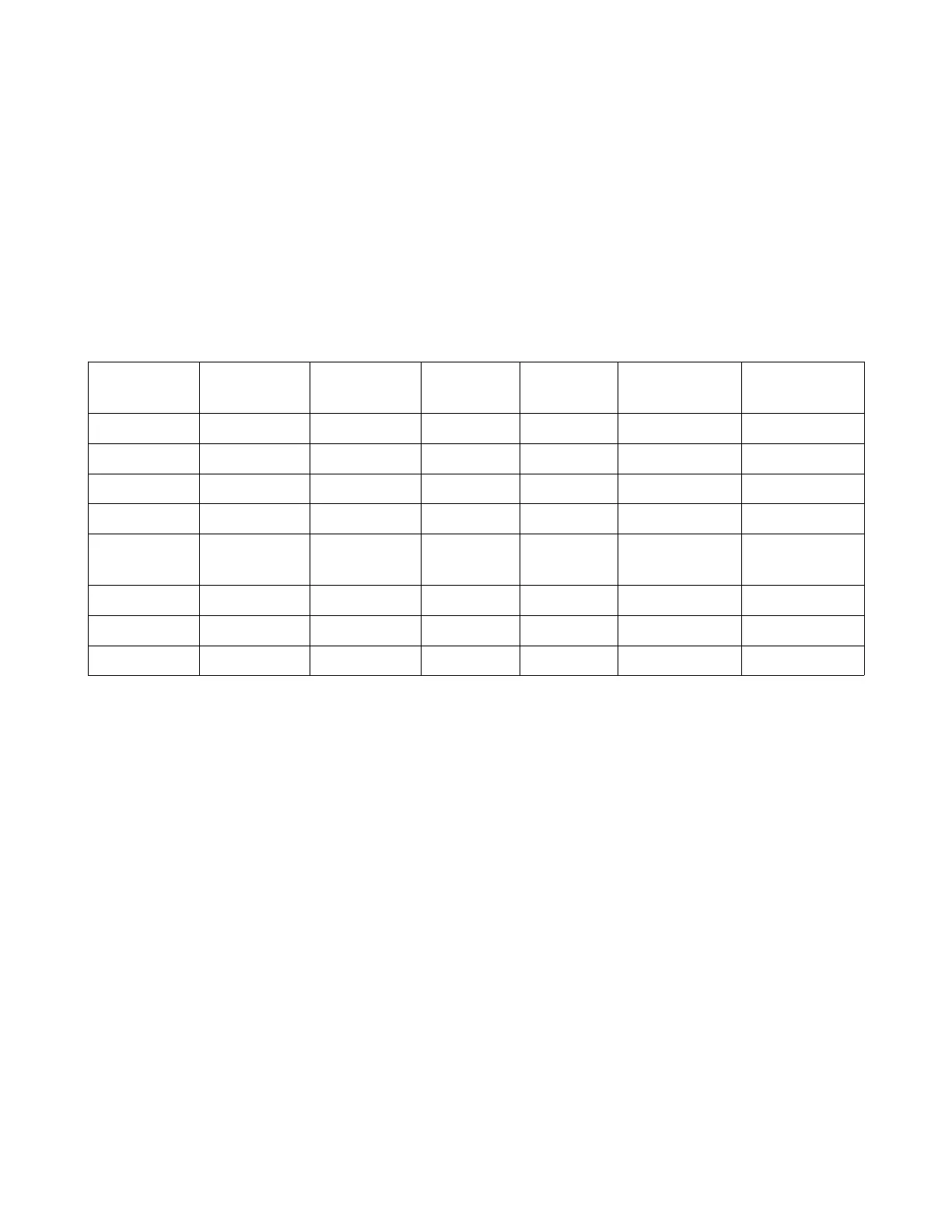
Figure 6: Input/Output Control Mapping
Input
Source
Index Level Switch
Types
Outputs Aux Control
Required
Optional Aux
Control
Analog 1-24 0-100% All All C1549 n-ANB ---
Panic 1 or 2 --- All All --- C1549 n-ANB
Aux 1-7 --- All All C1470 n-207 ---
DMX A or B 1-512 0-100% All All --- ---
DMX A (or
B) Status
A (or B) --- All All --- ---
Any DMX --- --- All All --- ---
Dimmer 1-512 0-100% All All --- ---
Zone Area & Zn # 0-100% All All --- ---
Inputs may be an actual hardware switch input such as an analog signal or auxiliary signal, or they may
be a virtual input such as a Zone# & level, a Panic, DMX status sense, or Dimmer# & level.
Switch types as found in the configuration program are “ON, OFF, TRACK or TOGGLE”.
ON = The specified input will turn on the specified output
OFF = The specified input will turn off the specified output
TRACK = The output switch will track the input signal
TOGGLE = The output switch will toggle between on & off with each successive toggle of the
input.
An output can be either one of the (8) auxiliary outputs, or a virtual output such as Panic or Take
Control. The auxiliary outputs require an additional C1549 control board, whereas the Panic or Take
Controls are virtual.
While there is flexibility in the design of the DX3 system, some of the I/O options require auxiliary
control boards as shown in Figure 6 above. The Control Source Example chart in Figure 5 shows some
of these possibilities and how they can be used.
DX3 Manual 13