MS50/TS50/TM50, Check & Adjust
65
5.4 Tilting Axis Adjustment (a)
Description This adjustment procedure determines the following instrument error:
Determination of
tilting axis error
step-by-step
The following table explains the most common settings.
a Tilting axis error
Step Description
Determine the horizontal collimation error (c) before starting this proce-
dure.
1. Main Menu: User\Check & Adjust
2. Check & Adjust Wizard
Select the option: Check & adjust the tilting axis
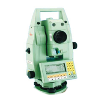
3. Face I measurement
Aim the telescope accurately at a target at about 100 m
distance or less if not possible. The target must be posi-
tioned at least 27°/30 gon above or beneath the hori-
zontal plane.
The procedure can be started in any telescope face.
4. Meas to measure and to continue to the
next screen.
The fine pointing must be
performed manually in both faces.
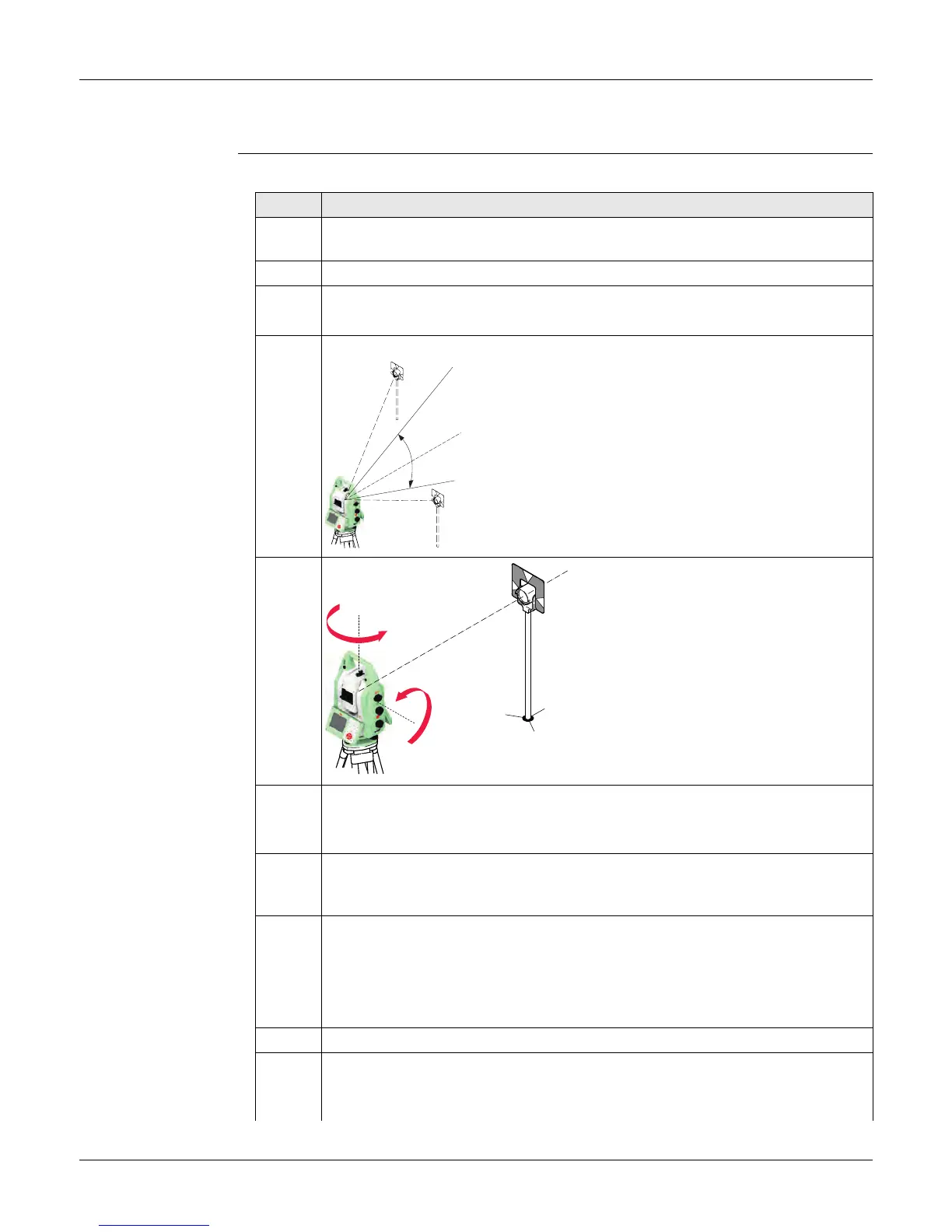
5. Face II measurement
Meas to measure the same target in the other face and to calculate the
tilting axis error.
If the error is bigger than the predefined limit, the procedure must be
repeated. The tilting axis measurements of the current run are then rejected
and not averaged with the results from previous runs.
6. Adjustment Status
No. of measurements: Shows the number of runs completed. One run
consists of a measurement in face I and face II.
σ a T-axis: shows the standard deviation of the determined tilting axis error.
The standard deviation can be calculated from the second run onwards.
Measure at least two runs.
7. Next to continue with the check & adjust procedure.
8. Select Add another calibration loop if more runs have to be added. Next
and continue with step 3.
005027_001
V=90°
+ 27°
- 27°
005026_001
180°
180°
 Loading...