15
15
A
B
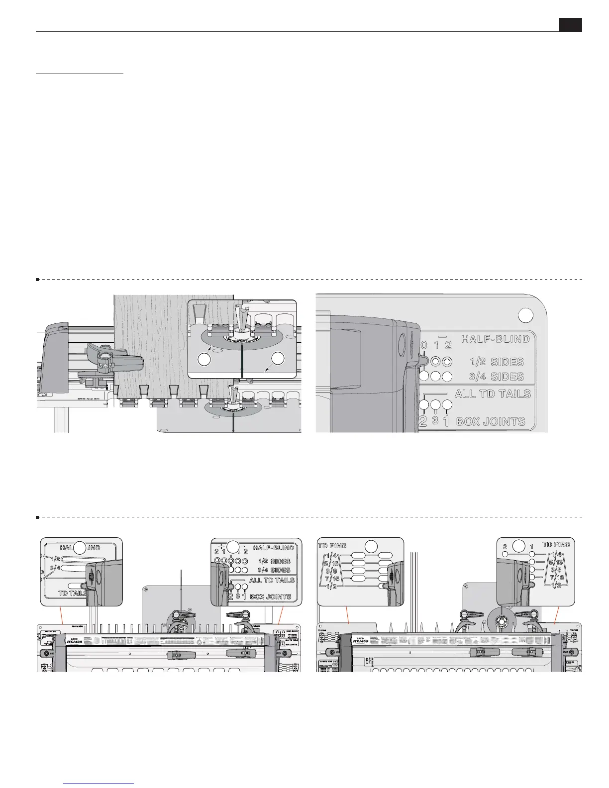
4-3 In this orientation, pin holes
A
and corresponding slots
B
are for half-blind dovetails, through tails and box joints.
C
D
A
Router Table Surface
Template Markings and Orientation
Frame Pin Positioning
Quick Reference Strips
Routing Position
Sidestops
Clamping
Backer Board
Router Table Surface
4-1
Make sure there are no ridges
A
anywhere on the router
table surface. The template must slide smoothly over the table top.
If the router table is not flat it will have the effect of changing the
bit height as the template moves across the table.
4-4 In this orientation, pin holes
C
and corresponding slots
D
are for through dovetail pins and half pitch through dovetail pins.
Template Markings and Orientation
4-2 The engraved side of the template always faces up. The
markings clearly identify which pin hole or slot to position
the frame pin into, based on the joint type and size. Template
orientation is shown in the next two steps.
IMPORTANT NOTE: Many of the images in this user guide show the “action” side of the jig, however the operator stands behind
the RTJ400, away from the chips and sawdust thrown off by the router bit.
RTJ400 OPERATION
CHAPTER 4
Basic Jig Functions
A