16
16
RTJ400 User Guide
Basic Jig Functions
Chapter 4
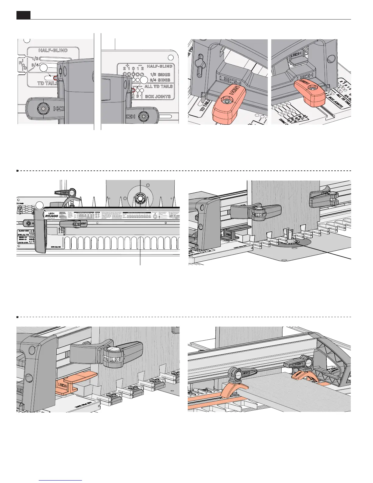
Frame Pin Positioning
4-5 The frame is positioned on the template by inserting the
frame pins into the pin holes
A
and slots
B
. The frame pins are
intended to be snug in the template holes.
To prevent damage
to the frame pin always remove the right frame pin first.
4-6
Be sure to latch the frame securely each time the frame
is repositioned.
Only when the frame is latched securely is it safe
to lift and or carry the jig by the handles.
Routing Position
4-8
Always use the right-hand side of the jig as shown above,
except where specified.
Note: When instructed to rout from right
to left, this is from the “operator’s” position, standing behind
the RTJ400.
Quick Reference Strips
4-7 Quick Reference strips
A
for each joint type are stored in
the slot on the top of the jig frame.
Sidestops
4-9
The adjustable sidestops are user set in a predetermined
position for box joints, or positioned against the edge of the
workpiece.
Clamping
4-10 Cam-action speed-clamps are exceptionally strong. The
clamp arms in conjunction with the machined texturing on the
template and frame ensure secure clamping.
B
A
A