43
43
3/8"
1/2"
1/4"
3/4"
0"
1"
143-500
173-500
Item No. Carbide Tipped
Bit Diameter
Item No.
Spiral HSS (Optional)
Item No. Spiral Solid Carbide (Optional)
173-500C
BOX JOINT BIT CUTTING DEPTH
C
D
RTJ400 OPERATION
CHAPTER 10
3/8" Box Joints
IMPORTANT SAFETY NOTE
Before using your Leigh RTJ400 you must have
completed the preparatory steps listed in the
previous pages, including reading the jig safety
recommendations in Chapter 3.
10-2 Bits, Guide Bushing and Stop Rod
⅜" box joints are routed with the included ⅜" straight bit 143-500, or optional 173-500 or 173-500C bits, the e10 guide bushing
(eBush), and the stop rod (for positioning the sidestop only). They can be routed in board thicknesses up to the maximum capacity
of the RTJ400 Template and the cutting depth of the bit, in this case, 1" [25.4mm].
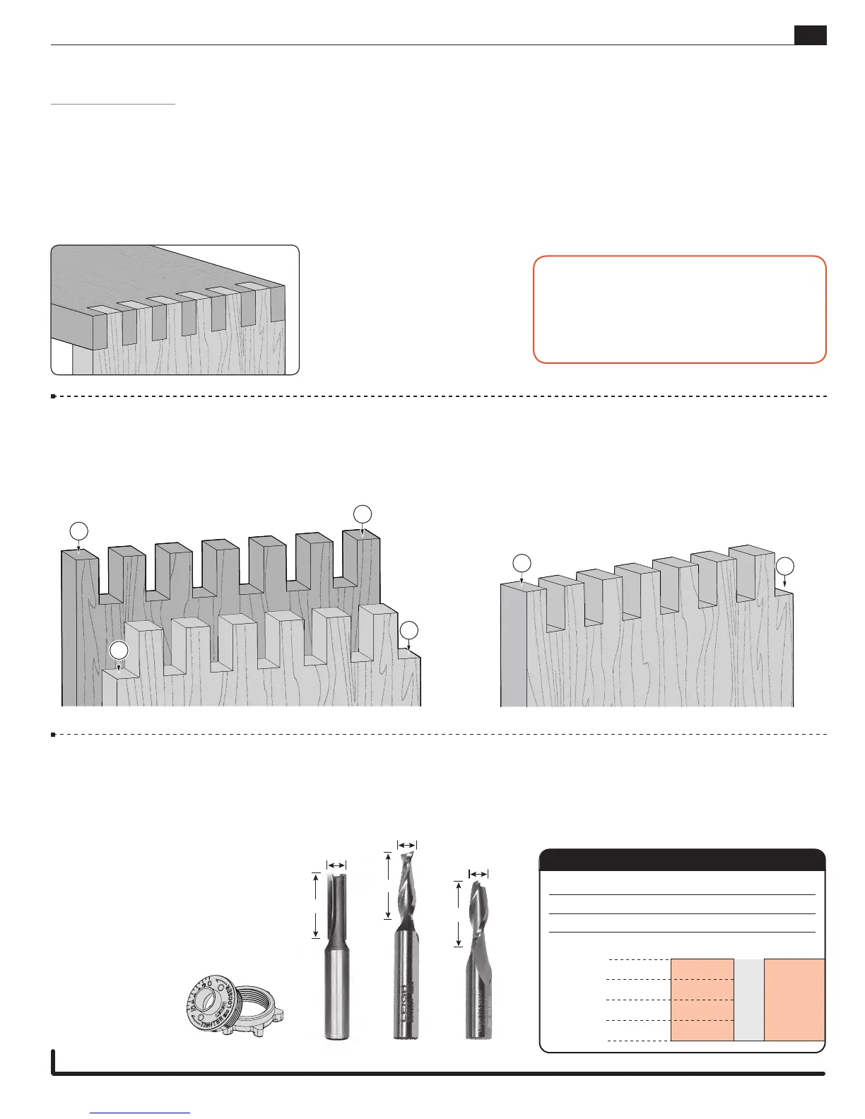
10-1 Getting Started
Review the drawing below. Symmetrical joints have pins
A
on both edges of one board, and sockets
B
on both edges of the mating
board. Asymmetrical joints have a pin
C
on one edge and a socket
D
on the other edge of each board.
SYMMETRICAL ASYMMETRICAL
A
A
B
B
3
/8
"
3
/8
"
1"
3
/8
"
1"
1"
143-500 173-500
(optional)
173-500C
(optional)
3/8" Box Joints
3/8" Half-Blind Box Joints
3/8" Box Joints
e10 eBush
(guide bushing)
stop rod
(for positioning sidestop)