2424
RTJ400 User Guide
Through Dovetail Joint Procedures
Chapter 7
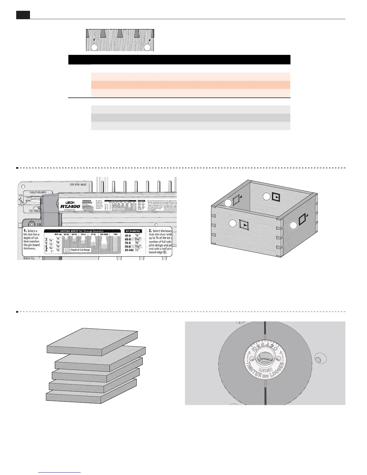
7-7 Fit the e10 eBush to the router table/router table insert. Set
the eBush to 5.
7-5 Making a Box Note the symbols indicating the inside
or outside of the pin and tail boards. When assembled with the
finished pieces properly oriented, any one of the pin ends will fit
any one of the tail ends.
Mark the inside faces of the tail boards
A
and outside faces of the pin boards
B
.
7-6 Use five similar boards (one for testing) about ¾"× 6¼" by
about 12" long [19mm × 159mm × 305mm]. Boards of different
thicknesses may also be joined.
IMPORTANT:
Read this whole chapter before routing any
boards.
7-3 Use this chart to determine the board width for your project. Through Dovetail joints may be routed in boards up to "
thick for pin boards and 1" thick for tail boards. Board widths are determined by the total number of full tails in the joint design.
Note: Board widths may be wider than the chart width by half of the dovetail bit diameter or less than the chart
width by one quarter of the dovetail bit diameter.
7-4 Use the Quick Reference strip to determine the correct
dovetail bit and guide bushing combination for the board
thickness, in this case, the Leigh e10 Guide Bushing and the
Leigh 80-500 bit.
A
A
B
B
A
B
Board widths are based on the number of full
tails
A
in your design. Board edges should
almost always end in a half-pin
B
.
Board Width Selection for Through Dovetails
No. of Tails 1 2 3 4 5 6 7 8 9 10
Inches
Min 1 ⁄" 3" 4 ⁄" 6 ⁄" 7 ⁄" 9 ¼" 10 ⁄" 12 ⁄" 13 ⁄" 15 ½"
Exact 1 ⁄" 3 ⁄" 4 ⁄" 6 ¼" 7 ⁄" 9 ⁄" 10 ⁄" 12 ½" 14 ⁄" 15 ⁄"
Max 1 ⁄" 3 ½" 5 ⁄" 6 ⁄" 8 ⁄" 9 ¾" 11 ⁄" 12 ⁄" 14 ⁄" 16"
No. of Tails 1 2 3 4 5 6 7 8 9 10
Millimeters
Min 37 76 116 156 196 235 275 315 355 394
Exact 40 80 119 159 199 239 278 318 358 398
Max 49 89 129 169 208 248 288 328 367 407