49
49
RTJ400 User Guide
Chapter 10
Box Joint Procedures - 3/8"
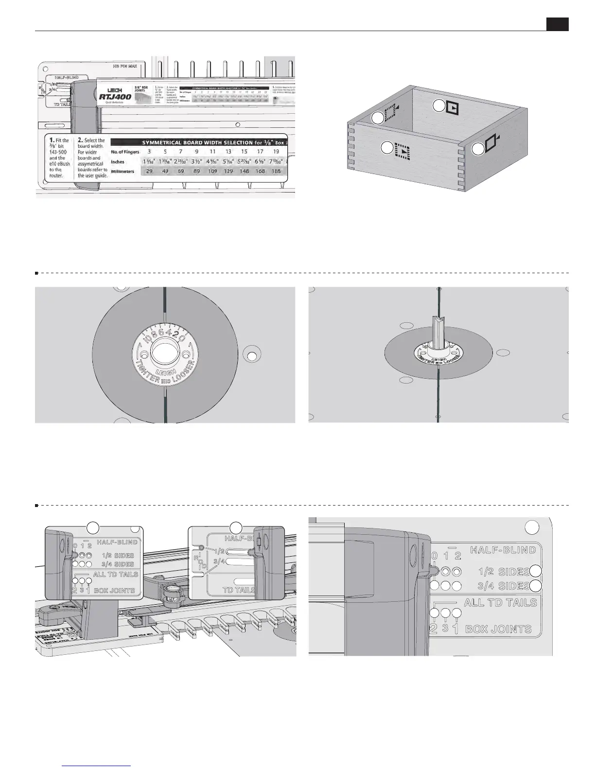
10-27 Fit the e10 eBush to the router table/router table insert.
If you have already determined the correct fit in the ⅜" box joint
chapter, use that setting, or alternatively use the Quick Fit Test,
Step 10-14.
10-25
Half-blind box joints are made using the same bit and
eBush as ⅜" box joints, however the
HALF-BLIND
section of the
template is used.
10-26 Note the symbols indicating the inside or outside of the
pin and tail boards. To make a box you will need to mark these
symbols on the inside faces of the tail boards
A
and outside faces
of the pin boards
B
.
10-28 With the router unplugged, install the supplied ⅜"
Leigh 143-500 bit. For cleaner routing use the optional ⅜" Leigh
173-500 (HSS) or 173-500C (solid carbide) spiral upcut bit,
available at leighjigs.com. Make sure the bit spins freely before
connecting the power.
A
10-29 Insert the right frame pin in the ½"
HALF-BLIND
"0" pin
hole
A
and the left frame pin in the ½"
HALF-BLIND
slot
B
.
Latch the frame.
Note: The HALF-BLIND pin hole settings refer
only to the thickness of the pin board (drawer side).
B
A
A
B
B
3/8" Half-Blind Box Joints cont.
B
A
10-30
NOTE:
Use the ½" row
A
for tail boards ⅜" [11mm]
to ⅝" [16mm] thick, and the ¾" row
B
for tail boards "
[17.5mm] to ⅞" [22mm] thick.