2626
RTJ400 User Guide
Through Dovetail Joint Procedures
Chapter 7
A A
A
B
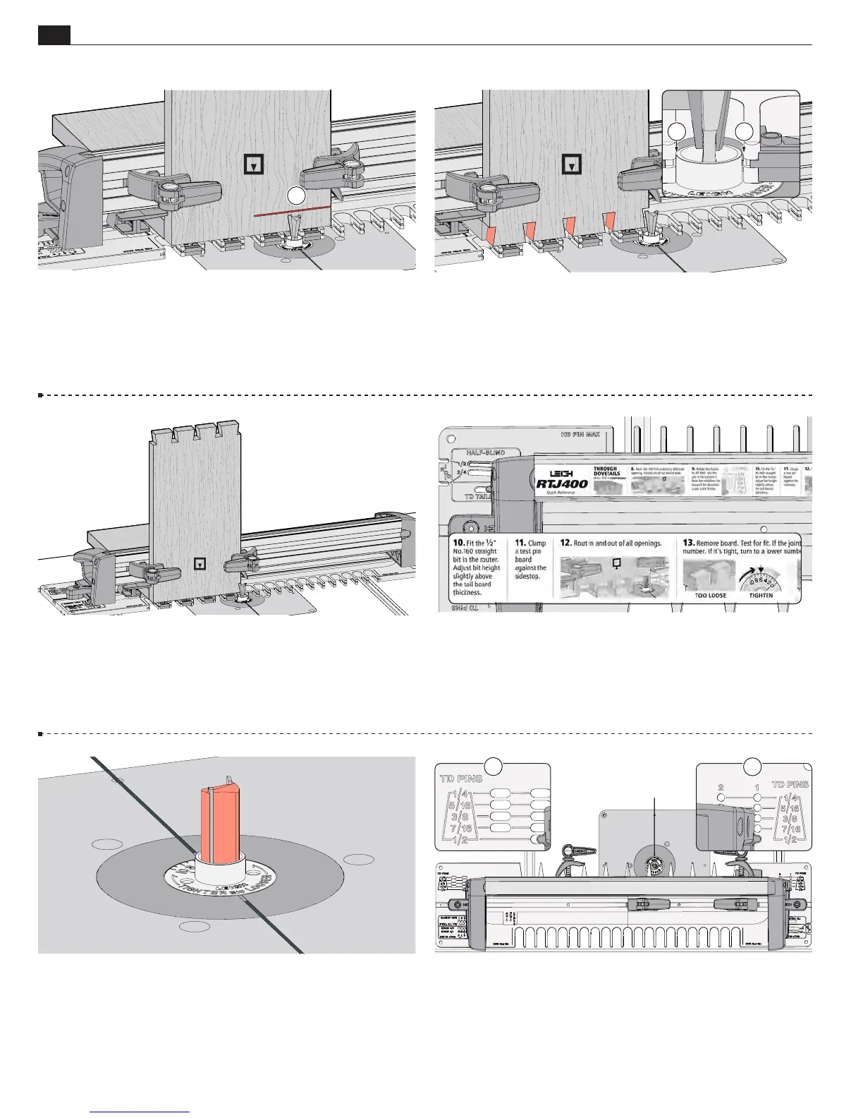
7-19 Rotate the frame to the
TD PINS
mode. Insert the right
frame pin in the
Column 1 TD PINS
hole that matches the dovetail
bit diameter just used to rout the tails, ½" in this example
A
, and
the left frame pin in the matching slot
B
. Latch the frame.
7-15 Rout in the first and every other opening, 1, 3, 5 and 7.
The eBush when set at 5 is slightly narrower than the opening
A
.
The eBush must touch one side of the opening as you enter
and the other side as you exit. Do not twist the jig on the table.
Keep the edge of the template square to the center line on the
table.
7-14
Position the jig and tail board close to the bit and adjust
the bit height to the center of the line
A
. Double check that
the bit still rotates freely.
IMPORTANT: Bit height determines the
flushness of the joint, so set your bit properly the first time.
Adjustments for flushness are near the end of the chapter.
7-16
Be sure the router bit has stopped moving before
unclamping the tail board.
Rotate tail board 1 keeping the same
face of the board against the jig. Rout the tails. Repeat 7-15 and
7-16 for tail board 2. Remove the tail board and backer board.
Disconnect the power and remove the 80-500 dovetail bit.
7-17 As instructed in the Quick Reference strip, always use the
½" [12.7mm] Leigh 160 straight bit or equivalent spiral bit to
rout the full pitch through dovetail pins.
7-18 With the router unplugged, fit the 160 straight bit to the
router and leave the e10 eBush set to 5.
Be sure the bit spins
freely within the guide bushing before reconnecting the power.
A