37
37
RTJ400 User Guide
Chapter 9
Half-Blind Dovetail Joint Procedures
B
B
A
9-13
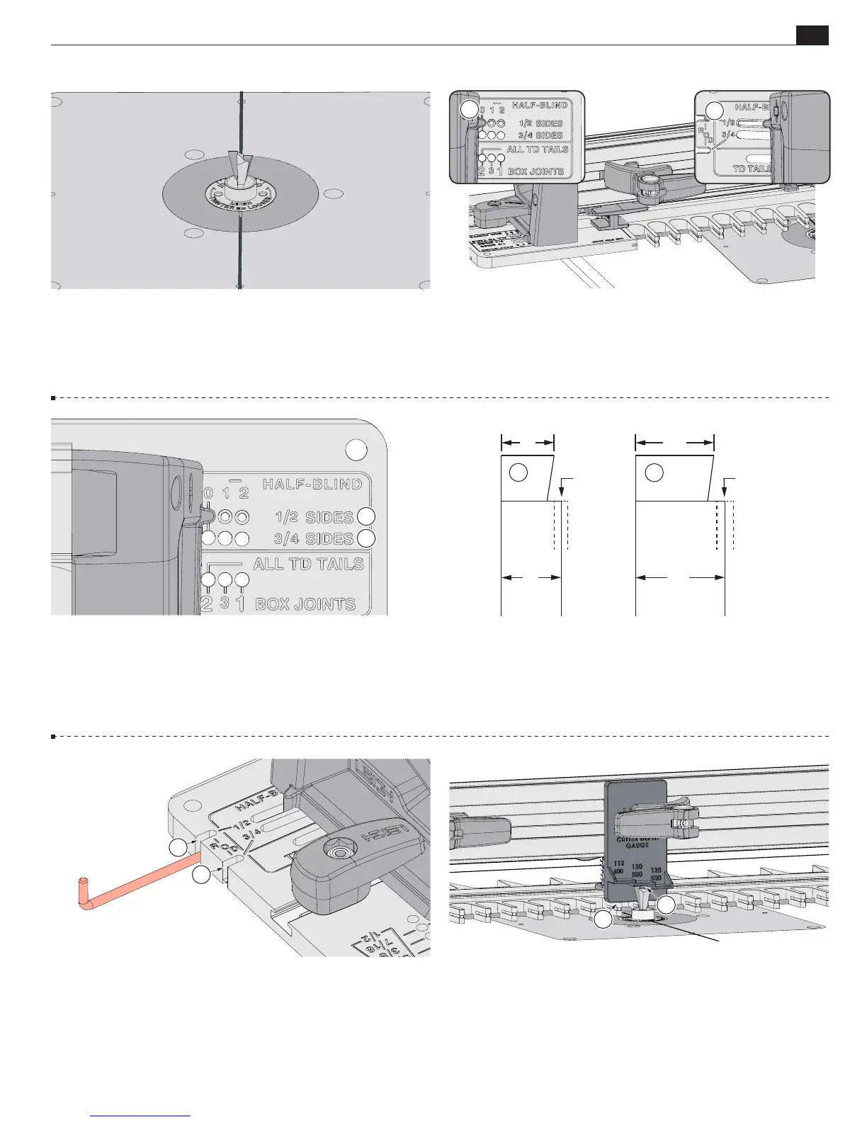
Bit Height:
Clamp the cutter depth gauge as shown, flush
on the template
A
. Raise the bit until it touches the bottom of
the gauge for the selected bit
B
. Double check that the bit
still rotates freely.
Hint:
As you raise the bit, slide a piece of paper
back and forth until it is trapped and snags on the bit.
A
9-10
NOTE:
Use the
½" SI DE S
row
A
for tail boards (sides) ⅜"
[9mm] to ⅝" [16mm] thick and the
¾" SIDES
row
B
for tail
boards " [17.5mm] to ⅞" [22mm] thick.
9-8 Unplug the router and install the Leigh 120-500 dovetail
bit.
Make sure the bit spins freely before reconnecting the power.
A
9-9 Insert the right frame pin in the
HALF-BLIND ½" SIDES
“O”
hole
A
and the left frame pin in the
½" HALF-BLIND
slot
B
.
Latch the frame.
Note: The HALF-BLIND pin hole settings refer
only to the thickness of the tail board (drawer side).
9-12 The Stop Rod. For tail boards (sides) from ⅜" [9mm]
to ⅝" [16mm] thick, insert the stop rod in the ½" slot
A
.
Note: For tail boards
⁄"
[17.5mm] thick or greater, the stop
rod is stored in the ¾" slot
B
.
9-11 When the frame pin and stop rod are in the ½" positions,
all tails will be this dimension
A
, regardless of actual board
thickness (dashed line). Similarly, when the frame pin and stop
rod are in the ¾" hole, all tails will be this dimension
B
, regardless
of actual board thickness.
⁄"
⁄"
⁄"
⁄"
⁄
"
to ⁄
" ⁄
" to ⁄
" or more
B
B
A
B
A