61
61
RTJ400 User Guide
Box Joint Procedures - 3/16"
Chapter 12
12-8 With the power disconnected from the router, install the
optional " Leigh 166 (HSS) or 166C (solid carbide) bit. Make
sure the bit spins freely in the bushing before reconnecting the
power. Optional bits available at leighjigs.com
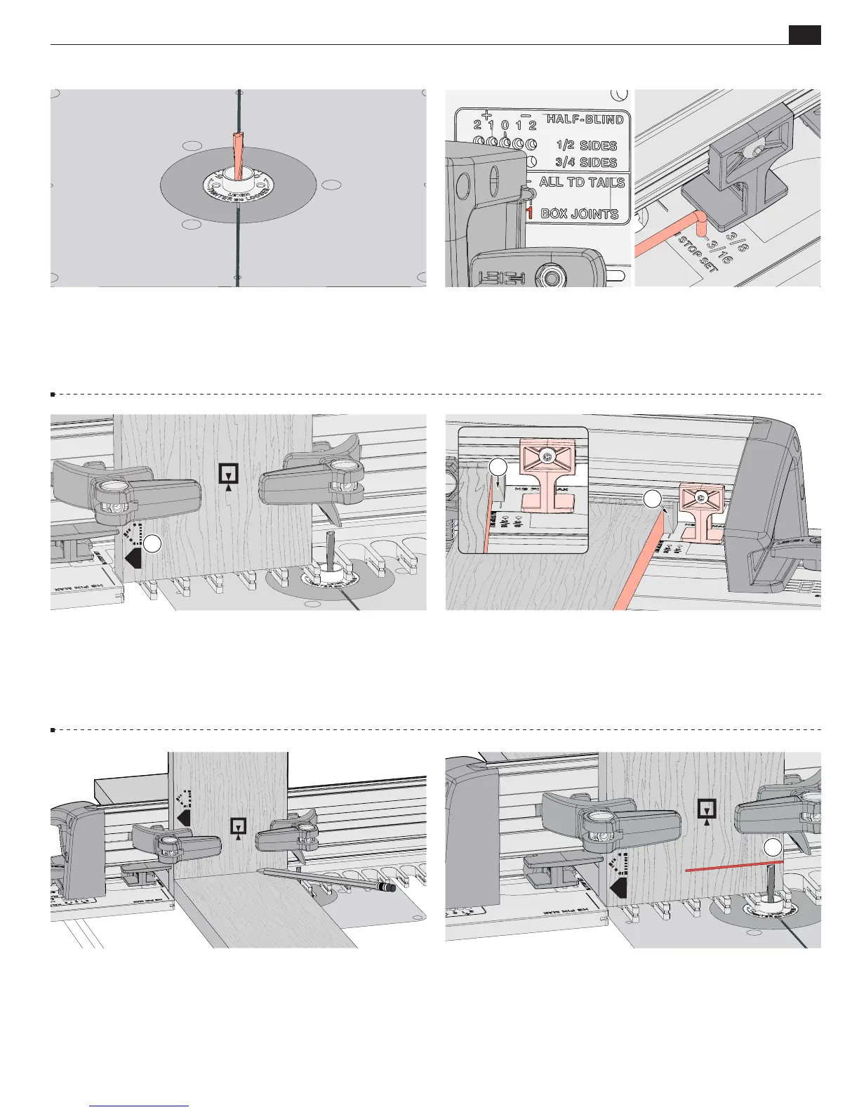
12-9
Insert the right frame pin in the
No.1 BOX JOINTS
hole and
the left frame pin in the
TD TAILS & BJ
slot. Latch the frame. Put
the short end of the stop rod into the
3/16"
BJ STOP SET
hole.
Slide the sidestop to lightly touch the rod and tighten the sidestop.
Store the stop rod in the ¾" slot.
12-10 Clamp pin board 1 vertically with the side edge against
the sidestop, the end edge flush on the template.
Always keep
the same side edge of the board to the sidestop when routing
box joints
A
.
A
A
12-12 Place the end of a socket board on the template and
pencil a line on the pin board.
12-11
Position a backer board at least " [4.5mm] from the
board edge
A
. This prevents the backer board from interfering
with the sidestop when the frame is repositioned in the following
steps. The backer board stays in place for the complete procedure.
Note: Clamp removed for clarity.
A
A
12-13 Adjust the bit until the tip is level with the center of the
pencil line on board 1
A
.
IMPORTANT: Bit height determines the
flushness of the joint, so set your bit properly the first time.
Adjustments for flushness if required are at the end of the chapter.
Double check that the bit still rotates freely.