10
Libelle andTirol:StraighteningandFoldingtheHandle‐Stem
Figure QF7:
Correctly installed handle‐stem.
view from side. The hinge at the
base of the handle stem (3) of
the Libelle and Tirol is at a 40
degree angle. This makes it
possible to fold the stem down
nicely to the side of the bike
(Figure QF3). Use the top quick‐
release (1) to adjust the handle‐
stem height by a couple of cm.
Use the bottom quick release
(3) or twist release (Figure QF9)
to securely hold the stem in an
upright, non‐folded position.
Minimum insertion mark (14)
must not be visible.
1
2
3
4
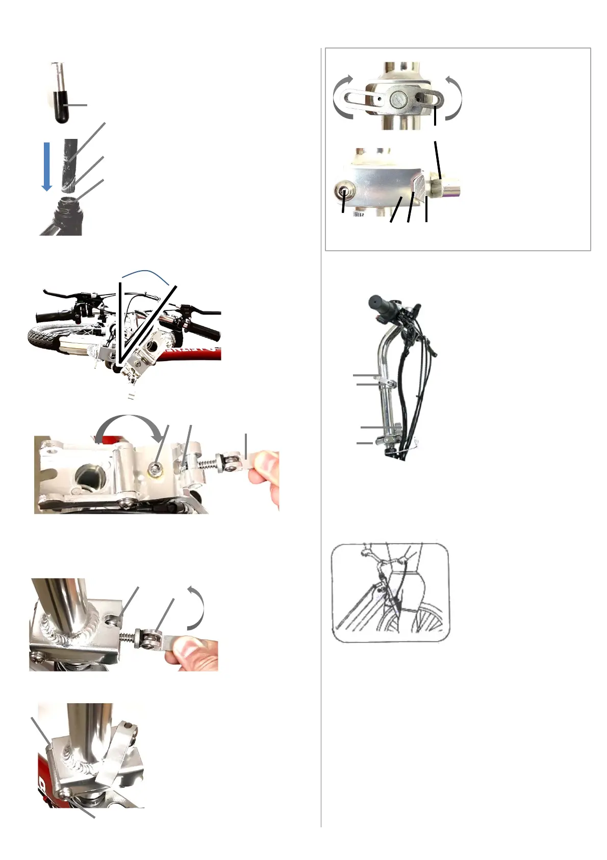
Figure QF1: view of base of stem from side.
If there is a black plastic cap (4) remove it to
expose the wedge nut (5, Figure QF2)
7
Figure QF4: view from top, folded handle‐stem. While
pushing quick release lever (10) down, carefully fold stem
UP in the direction shown until it’s fully closed. For twist‐
release refer to Figure QF9.
8
5
6
Figure QF3: view
from top.
Handle‐stem is
folded to the
side of bike.
Note the angle of
about 40
degrees.
Angle
9
10
Figure QF5: view
from top, closed
handle‐stem.
Move the quick
release lever (11)
up through the
slot (12).
11
12
Figure QF6: view from top. Close
the quick‐release lever as shown.
Check that the stem is stable and
safely closed. If the stem is loose
you may have to tighten the quick
release nut (9, Figure QF4) or the
hinge bolts (13)
13
13
To align stem with wheel,
walk to front of bike, put
wheel between your legs
and adjust handle‐stem
position. If major centering
adjustments are needed,
release attachment bolt (8,
Figure QF4) by a few turns,
centre stem, then tighten
bolt to 14 Nm.
FigureQF8
CAUTION! Pinching hazard: Take care and stay clear of
moving Parts. Fold carefully. Take care not to damage or
scratch the bike during the folding procedure. Adjust
position of quick release levers if needed. Make sure to
leave enough slack for all wires to avoid damaging wires
while folding. Make sure handle‐stem is safely attached
before each ride. Refer to quick‐release section of manual
if needed.
WARNING! Make sure the stem is installed safely and
that the attachment bolt and release mechanisms are
tight before each ride. Failure to do so may result in
serious injury.
©LeitnerPtyLtd2020
14
Figure QF2: Installation of stem: Insert
wedge‐nut (5) and handle‐stem (6) into
head tube (7) of bicycle frame as shown in
Figure QF2 (black stem is shown). If wedge‐
nut (5) does not fit into head tube (7),
loosen attachment bolt (8, Figure QF4)by
several turns anti‐clockwise and try again.
Push stem down in direction of arrow shown
(Figure QF2). Make sure minimum insertion
mark (6) on handle‐stem is not visible after
stem is installed. Tighten attachment bolt
(8, Figure QF4) to 14 Nm.
Close
Open
15
16 17 18
Figure QF9.
If your stem has a twist
release (15) turn it in the
directions of the arrows
shown to open or close.
View from side:
If fully closed, there must
be no gap (17) between
the wedge (18) and the
body (16).
If the stem is loose you
may have to tighten the
hinge bolts (19).
19