EN-10
4 MACHINE ADJUSTMENTS
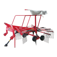
Put the machine into the working position as follows:
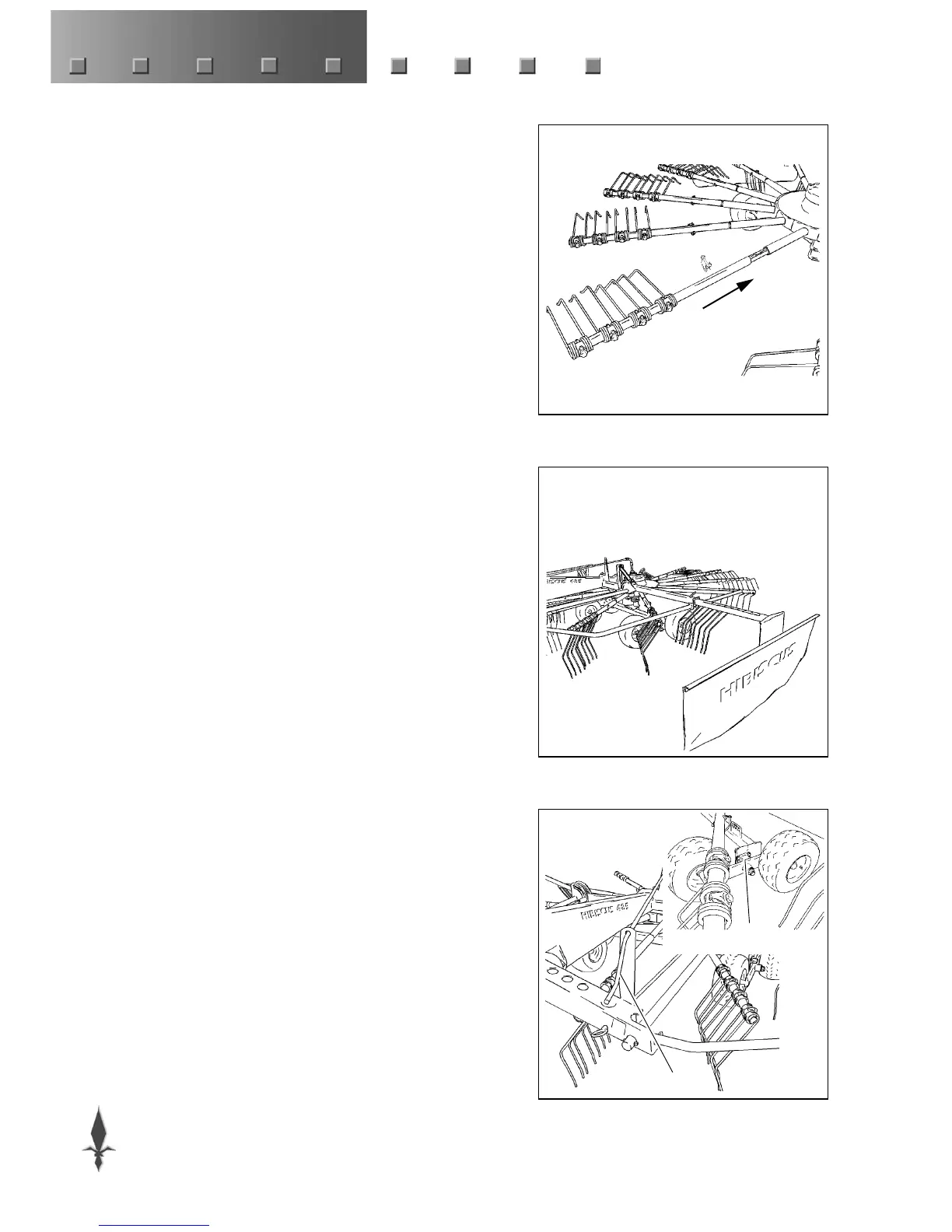
- Slide the tine arms onto the rotor (fig. 6).
- Pull out the locking bar and fold down the protection guard. Then
slide the bar back into the locked position and check that it is
properly secured.
This check is to be carried out on either side of the machine.
- Unlock the trail device by placing the locking pin (fig. 5) in the
top position.
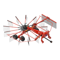
4.1 Swath width
- Slide the swath curtain outwards and lock it by means of the
locking pin (fig. 7).
Adjustment is dependent upon crop quantity and desired working
width.
Select a position in which there is a smooth flow of crop material
between the rotor and the swath curtain without build-up of
material.
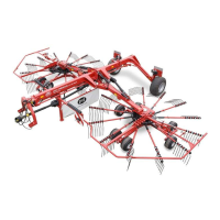
4.2 Working height
- Adjust the rotor in a horizontal or slightly inclined (forward)
position by means of the top link.
If the required height cannot be obtained with the help of the spindle
adjustment, try this by adjusting the tandem wheels to any of the 4
possible positions.
- Adjust the working height roughly by positioning the wheels (A,
fig. 8).
The end piece can also be fitted upside down, which reduces the
adjustment to half. This makes it possible to adjust the rotor at the
swath side (LH) a half-position lower, so that a larger crop
volume can be handled.
Fit the bolts spaced as widely apart as possible to achieve a
reliable connection.
- Adjust the exact height by means of the spindle B. The tines
should only just touch the ground.
Control of the spindle is easier while the machine is slightly lifted.
6
7
8
A
B
 Loading...