7CH Essential Instructions R1.0 2022/11/08
4
To activate User-set Failsafe, proceed as follows:
1. Power ON the transmitter. Set sticks and switches to the positions required on loss of signal.
2. Power ON the receiver.
3. After 3 seconds but within 60 seconds of powering ON the receiver, press and hold the Failsafe button F.
4. Release button F when the green Setup LED turns ON, showing that the receiver has registered the
failsafe values.
5. Test failsafe (carefully) by turning off the transmitter (on the bench, not in flight!).
The receiver will retain the failsafe values until the procedure is repeated or the receiver is reset.
To cancel User-set Failsafe:
1. Power ON the receiver. If User-set Failsafe is active, the green Setup light will be ON.
2. After 3 seconds but within 60 seconds of power ON, press and hold button F.
3. Release button F when the green Setup LED turns OFF, indicating No-pulse mode.
Setup, if you are not wanting to use the stabilization function, is now complete.
Just a check: stabilization is not active if the red programming LEDs R1, R2 and R3 shown in the
diagram under “LED Identification“ on page 4 are not lit. This is how the receiver is delivered.
Step 4: Activating Stabilization – if required.
Programming the Receiver
If the three red Programming LEDs (in a row in the centre of the receiver) are all OFF, stabilization is NOT active,
and the receiver operates as a standard 7 channel DSMX/DSM2™ compatible receiver.
Activating stabilization requires programming the receiver, as explained below. Note that if stabilization is
active, certain mixes, notably Delta Wing (elevons) and V-Tail, MUST be done in the receiver, not the
transmitter.
WARNING: If doing any programming of an electric powered model with the motor connected, please remove
the propeller for your safety!
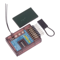
LED Identification
All setup is done by using the three buttons (B, C, F), and for some functions, a bind plug on channel 5 or 6.
Individual stability gain adjustments for Roll (Aileron), Pitch (Elevator), and Yaw (Rudder) are done with the
three rotary “pots” labelled A, E and R in the diagram below.
The diagram, together with the one on
page 2, identifies the buttons, pots
(potentiometers) and various indicator
LEDS. Please review them carefully.
With the receiver powered ON, locate the
three green and three red programming
lights (G1, G2, G3 and R1, R2, R3).
Press button C for no more than 2
seconds to identify these lights.
Also locate the position of the blue and
green Setup lights and the red and green
Status lights, as shown in the picture.