10CH TXT Essential Instructions v1.docx 2024-09-05 2
The original version of the LM0087 used LEDs and buttons for programming. The new version, introduced in
August 2024 and referred to as the LM0087X, added the Text Display feature to simplify programming, but it
also retains the earlier lights and buttons programming approach as an option.
Connections
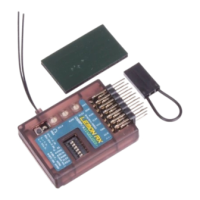
The receiver has six sets of pins on each end of the case: channels 1-10 are arranged in the usual Spektrum order
of T,A,E,R,G,Aux1,Aux2,Aux3,Aux4,Aux5. The channel 10 pins (Aux5) can also function as a normal bind plug
connector and are labelled accordingly. Channels 8 and 9 pins can be used for setting up the receiver (hence the
S.Ch and Mix labels) but these options can be ignored if Text Display is used. There are optional isolated BEC
(separate power source) inputs on each end labelled BEC1 and BEC2. In addition, there are connectors for an
optional satellite receiver and either an optional voltage/current sensor or a simple voltage probe for telemetry.
Note that channel 1 is the second set of pins and that the satellite and sensor connectors are identical but
labelled. Don’t mix them up. The receiver has a built-in barometric sensor which can provide altitude and
vertical speed (vario) data.
As delivered, the Lemon 10-channel receiver has stabilization disabled and no internal mixes set. Out of the
packet it functions as a standard ten channel DSMX/DSM2™-compatible receiver.
To use the receiver without stabilization, the only setup you might want to do is to change the default No-pulse
failsafe to User-set, as explained in Step 3 on page 3. In the unstabilized state, any other required programming,
such as mixes, will be done in the transmitter, as with other regular receivers.
Setting Up the LM0087X Receiver
Step 1: Powering the Receiver
The receiver requires a power supply between 4.0v and 8.5v that can deliver the required current to the servos
without dropping below 4v. The most common source is likely to be an ESC (Electronic Speed Controller) which
will supply 5v to the receiver and servos. Most electric powered planes will use this arrangement and power will
automatically be provided through the Throttle connection to channel 1.
The 10 servo connectors have common V+ and Ground pins, as is normal practice, although voltage is normally
supplied on the Throttle channel from the ESC. However, this receiver has, in addition, isolated independent
BEC1 and BEC2 power input pins which permit different power arrangements which can increase reliability. (You
can’t use these connectors to supply power to anything – they are inputs only.)
The three common ways of powering the receiver are: