10CH TXT Essential Instructions v1.docx 2024-09-05 9
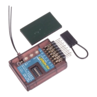
Table 1 shows how the servos should be assigned to the first 8 receiver channels and the corresponding LED
display. Channels 9 and 10 can be used for anything. Plug the servos and ESC into the appropriate slots on the
receiver. Normally, the Stabilization ON/OFF channel slot (channel 7 by default or channel 5 if set as an option)
will be empty, as it is used internally by the receiver.
Table 1: Configuration for Various Model Types (Stabilization Options)
Conventional
(one Ail channel)
Conventional
(two Ail channels)
V-Tail
(two Ail channels)
* Channel 5 (Gear) can be used for Stabilization ON/OFF on 6 channel transmitters but this is unlikely for the 10 channel
receiver where it will normally be used as a normal servo output. Set wing type (in the Aircraft Type menu) as shown;
in all cases, the tail type is Normal, even for a V-Tail model.
6. Verify control directions, adjust centring and servo throws
Power ON. Use the Stabilizer ON/OFF switch to turn stabilization OFF (green Status light OFF). Be sure you know
which way is OFF in case you need to use it in a hurry!
With trims in neutral, adjust servo arms and linkages to align your control surfaces. Use only a minimum of
subtrim on the transmitter for fine tuning. Servo arms should be at right angles to push rods to ensure equal
movement in both directions.
Adjust transmitter reversing so that all servos work in the correct direction in response to the sticks. Note that
where elevon, V-tail or flaperon mixing is involved it may be necessary to interchange the two servo connectors
and/or reverse controls to get the correct action.
With travel (limits) and control rates at 100%, check that control surface throws are at the recommended
maximums for the model and adjust linkages if necessary. Note that adjusting throws in the transmitter will not
affect stabilization responses, so throws need to be set mechanically to give the stabilizer an appropriate
amount of control; the exact amount is not critical, as gain will later be used to adjust stabilization, but it should
be reasonably close.
7. Test stabilization response and directions
Turn the three on-board gain adjustment pots fully clockwise to maximize action.
2
Set the Stabilizer ON/OFF
switch to ON (green Status light ON). Sharply move the plane in each of the three flight axes and verify that the
control surfaces move momentarily to oppose the disturbance. See diagram below.
HINT: If you find it hard to see the response direction, put your finger on the hinge line of the control surface. It
is easier to feel a short pulse than see it.
2
If you are using channel 8 for Master Gain, set it temporarily to the middle or high end of its range.