Page 11
Table 5
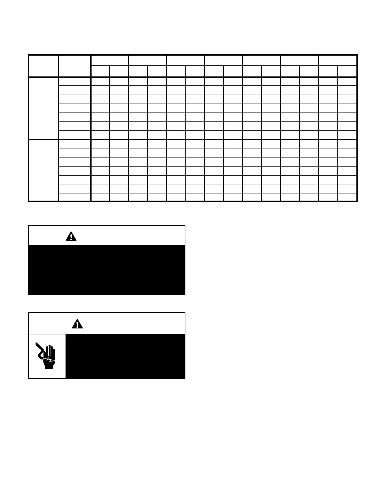
Normal Operating Pressures In psig (liquid and suction +/- 2 psig)*
Unit /
Out. Coil
-018 -024 -030 -036 -042 -048 -060
Device
Air Temp.
F (
C)
LIQ. SUC. LIQ. SUC. LIQ. SUC. LIQ. SUC. LIQ. SUC. LIQ. SUC. LIQ. SUC.
65 (18.3) 154 62 165 68 170 76 168 67 178 67 163 68 189 72
75 (23.9) 181 68 190 73 199 78 195 71 202 70 190 71 203 74
85 (29.4) 210 73 219 77 231 80 224 75 235 71 220 74 233 77
10ACC /
95 (35.0) 237 77 250 80 264 81 255 78 270 74 251 77 265 79
105 (40.6) 272 82 282 83 300 82 289 82 308 78 288 79 301 82
110 (43) 288 83 301 84 321 83 305 83 326 79 307 80 319 83
115 (45) 306 85 317 85 339 84 324 84 347 80 325 82 339 84
65 (18.3) 156 68 162 73 170 76 162 70 173 73 159 71 170 74
75 (23.9) 180 70 189 74 199 78 187 74 201 74 188 72 201 76
85 (29.4) 208 72 218 75 231 80 219 75 234 74 220 73 234 77
10ACC /
95 (35.0) 237 73 249 77 264 81 253 77 269 75 251 76 270 79
105 (40.6) 268 75 285 78 300 82 291 79 307 76 290 77 309 79
110 (43) 284 76 301 79 321 83 310 80 326 77 309 78 331 80
115 (45) 302 77 321 81 339 84 329 81 346 78 328 79 351 81
*These are typical pressures only. Indoor evaporator match up, indoor air quality, and evaporator load will cause the pressures to vary.
IMPORTANT
Use table 5 to perform maintenance checks. Table 5
is not a procedure for charging the system. Minor
variations in these pressures may be due to differ-
ences in installations. Significant deviations could
mean that the system is not properly charged or that
a problem exists with some component in the sys-
tem. See table 5.
E - Maintenance
WARNING
Electric shock hazard. Can cause inju-
ry or death. Before attempting to per-
form any service or maintenance, turn
the electrical power to unit OFF at dis-
connect switch(es). Unit may have
multiple power supplies.
Maintenance and service must be performed by a qualified
installer or service agency. At the beginning of each cool-
ing season, the system should be checked as follows:
1 - Clean and inspect the condenser coil. The coil may be
flushed with a water hose. Make sure power is off be-
fore cleaning.
2 - Visually inspect connecting lines and coils for evi-
dence of oil leaks.
3 - Check wiring for loose connections.
4 - Check for correct voltage at unit (unit operating).
5 - Check the compressor and condenser fan motor amp-
draw.
NOTE - If the owner complains of insufficient cooling,
the unit should be gauged and the refrigerant charge
should be checked. Refer to the charging section in
this instruction.
Evaporator Coil
1 - Clean coil, if necessary.
2 - Check connecting lines and coils for evidence of oil
leaks.
3 - Check the condensate pan line and clean it if neces-
sary.
Indoor Unit
1 - Clean or change filters.
2 - Adjust blower speed for cooling. The pressure drop over
the coil should be measured to determine the correct
blower CFM. Refer to the unit information service manu-
al for pressure drop tables and procedure.
3 - Belt Drive Blowers - Check belt for wear and proper
tension.
4 - Check all wiring for loose connections
5 - Check for correct voltage at unit (blower operating).
6 - Check amp-draw on blower motor.

 Loading...