Page 3
I - GENERAL
Make sure all power is disconnected before
beginning electrical service procedures.
DANGER
10ACC condensing units are available in 1 -1/2, 2, 2 -1/2, 3, 3
-1/2, 4 and 5 ton capacities.
All major components (indoor blower and coil) must be
matched according to Lennox recommendations for the com-
pressor to be covered under warranty. Refer to the Engineer-
ing Handbook for approved system matchups. A misapplied
system will cause erratic operation and can result in early
compressor failure.
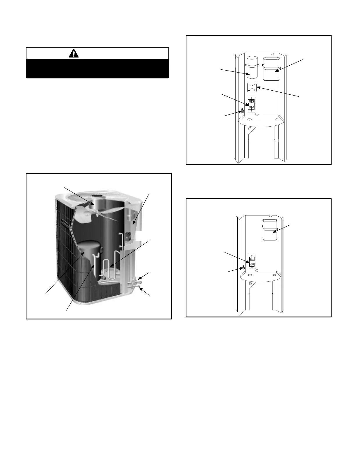
II - UNIT COMPONENTS
Unit components are illustrated in figure 1.
COMPRESSOR
CONTROL
BOX
SUCTION LINE
SERVICE VALVE
SUCTION LINE
OUTDOOR
FAN/MOTOR
10ACC UNIT COMPONENTS
FIGURE 1
LIQUID LINE
SERVICE VALVE
DISCHARGE
LINE
FIGURE 2
DUAL CAPACITOR
(C12)
START
CAPACITOR (C7)
(option only)
POTENTIAL
RELAY (K31)
(option only)
COMPRESSOR
CONTACTOR
(K1)
10ACC UNIT CONTROL BOX
RECIPROCATING COMPRESSOR
GROUNDING
LUG
FIGURE 3
DUAL CAPACITOR
(C12)
COMPRESSOR
CONTACTOR
(K1)
10ACC UNIT CONTROL BOX
Scroll Compressor
GROUNDING
LUG

 Loading...