Page 35
14ACX SERIES
WHEN TO CHARGE?
Warm weather best
Can charge in colder weather
CHARGE METHOD? Determine by:
Metering device type
Outdoor ambient temperature
REQUIREMENTS:
Sufficient heat load in structure
Indoor temperature between 70‐80ºF
(21-26ºC)
Manifold gauge set connected to unit
Thermometers:
- to measure outdoor ambient
temperature
- to measure liquid line temperature
- to measure suction line
temperature
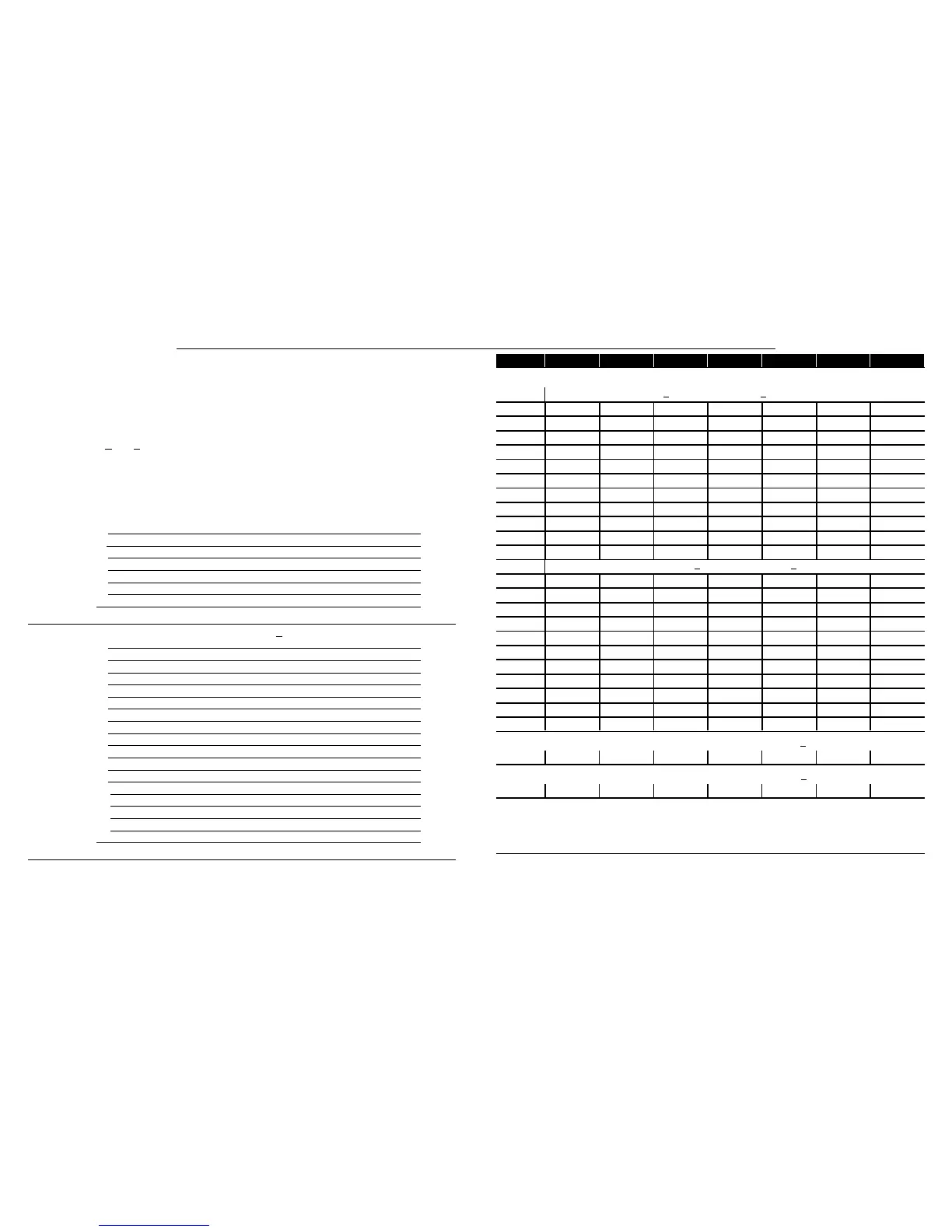
TXV
RFC
APPROACH OR
SUBCOOLING
WEIGH‐INSUPERHEAT
65ºF
(18.3ºC) and
Above
START: Determine how refrigerant is metered
39ºF
(3.8ºC) and
Below
Which
metering
device?
WEIGH‐IN
64ºF
(17.7ºC) and
Below
40ºF
(4.4ºC) and
Above
Figure 24. Determining Charge Method
Liquid Line Set Di
ameter
Ounces per 5 feet (g per 1.5 m) adjust from
15 feet (4.6 m) line set*
3/8” (9.5 mm)
3 ounce per 5' (85 g per 1.5 m)
Refrigerant Charge per Line Set Length
NOTE — The above nameplate is for
illustration purposes only. Go to actual
nameplate on outdoor unit for charge
information.
NOTE — Insulate liquid line when it is routed through areas where the surrounding ambient temperature could become higher than the
temperature of the liquid line or when pressure drop is equal to or greater than 20 psig.
CALCULATING SYSTEM CHARGE FOR OUTDOOR UNIT
VOID OF CHARGE
If the system is void of refrigerant, first, locate and repair any leaks and then weigh in the refrigerant charge into the
unit. To calculate the total refrigerant charge:
Amount specified on
nameplate
Adjust amount. for variation
in line set length listed on
line set length table below.
Total charge
+
=
WEIGH IN (RFC AND TXV)
Figure 25. Using HFC-410A Weigh In Method
 Loading...