CHARGING INFORMATION
FOR COMPLETE CHARGING DETAILS, REFER TO THE OUTDOOR UNIT INSTALLATION INSTRUCTION.
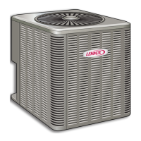
14ACX
-
-
-
-
-
-
-
7 -
-
5
-
Table 1- Normal Operating Pressures
1
°F(°C)
2
TXV System - Liquid Line ( + 10 psig) / Suction Line ( + 5 psig)
65 (18) 230 / 138 220 / 125 226 / 129 238 / 132 233 / 142 236 / 138 233 / 139 280 / 130 239 / 133 239 / 133
75 (24) 265 / 140 250 / 130 259 / 134 273 / 138 256 / 143 273 / 141 272 / 141 310 / 136 278 / 136 278 / 136
85 (29) 307 / 142 300 / 142 301 / 140 316 / 142 299 / 145 318 / 143 315 / 142 320 / 140 323 / 138 323 / 138
95 (35) 351 / 144 350 / 145 348 / 142 366 / 144 343 / 146 366 / 146 361 / 144 390 / 149 370 / 140 370 / 140
105 (41) 407 / 145 410 / 149 399 / 144 420 / 147 389 / 148 417 / 148 413 / 145 430 / 150 415 / 143 415 / 143
115 (45) 466 / 147 470 / 155 456 / 146 480 / 149 452 / 151 475 / 151 465 / 148 499 / 155 476 / 147 476 / 147
°F(°C)
2
RFC System - Liquid Line ( + 10 psig) / Suction Line ( + 5 psig )
65 (18) 232 / 124 210 / 122 229 / 128 241 / 131 228 / 131 248 / 135 232 / 125 250 / 126 244 / 125 244 / 125
75 (24) 267 / 131 240 / 127 261 / 132 277 / 136 263 / 138 285 / 141 268 / 133 300 / 134 281 / 131 281 / 131
85 (29) 307 / 138 300 / 142 305 / 138 321 / 141 306 / 144 327 / 145 312 / 140 350 / 135 324 / 136 324 / 136
95 (35) 351 / 143 350 / 142 349 / 142 366 / 145 348 / 148 372 / 149 357 / 144 380 / 148 370 / 141 370 / 141
105 (41) 400 / 148 400 / 147 396 / 146 416 / 149 395 / 151 421 / 152 406 / 149 420 / 149 418 / 145 418 / 145
115 (46) 457 / 153 450 / 150 449 / 150 480 / 152 453 / 155 476 / 154 460 / 152 490 / 150 471 / 147 471 / 147
Table 2- Approach (APP) Values
3
-TXV System - ºF (ºC) + 1ºF (0.5ºC)
65 (18) 4 (2.2) 4 (2.2) 2 (1.1) 2 (1.1) 3 (1.7) 6 (3.3) 9 (5.0) 7 (3.9) 8 (4.4) 8 (4.4)
75 (24) 5 (2.8) 4 (2.2) 4 (2.2) 5 (2.8) 3 (1.7) 8 (4.4) 9 (5.0) 8 (4.4) 9 (5.0) 9 (5.0)
85 (29) 6 (3.3) 5 (2.8) 6 (3.3) 8 (4.4) 4 (2.2) 8 (4.4) 8 (4.4) 8 (4.4) 9 (5.0) 9 (5.0)
95 (35) 5 (2.8) 5 (2.8) 5 (2.8) 7 (3.9) 4 (2.2) 8 (4.4) 8 (4.4) 8 (4.4) 9 (5.0) 9 (5.0)
105 (41) 3 (1.7) 5 (2.8) 5 (2.8) 6 (3.3) 4 (2.2) 8 (4.4) 8 (4.4) 8 (4.4) 9 (5.0) 9 (5.0)
115 (45) 3 (1.7) 4 (2.2) 4 (2.2) 6 (3.3) 5 (2.8) 8 (4.4) 8 (4.4) 9 (5.0) 9 (5.0) 9 (5.0)
Table 3- Subcooling (SC) Values
4
-TXV System - ºF (ºC) + 1ºF (0.5ºC)
65 (18) 10 (5.6) 3 (1.7) 11 (6.1) 13 (7.2) 9 (5.0) 10 (5.6) 6 (3.3) 8 (4.4) 6 (3.3) 8 (4.4)
75 (24) 6 (3.3) 3 (1.7) 8 (4.4) 9 (5.0) 7 (3.9) 7 (3.9) 6 (3.3) 8 (4.4) 5 (2.8) 7 (3.9)
85 (29) 6 (3.3) 3 (1.7) 6 (3.3) 7 (3.9) 7 (3.9) 7 (3.9) 6 (3.3) 8 (4.4) 5 (2.8) 8 (4.4)
95 (35) 6 (3.3) 3 (1.7) 6 (3.3) 8 (4.4) 7 (3.9) 7 (3.9) 6 (3.3) 8 (4.4) 4 (2.2 7 (3.9)
105 (41) 10 (5.6) 3 (1.7) 7 (3.9) 9 (5.0) 7 (3.9) 7 (3.9) 6 (3.3) 8 (4.4) 4 (2.2) 6 (3.3)
115 (46) 10 (5.6) 4 (2.2) 8 (4.4) 10 (5.6) 6 (3.3) 7 (3.9) 5 (2.8) 7 (3.9) 3 (1.7) 6 (3.3)
1
Typical pressures; indoor evaporator match up, indoor air quantity, and
evaporator load will cause the pressures to vary.
2
Temperature of air entering outside coil.
3
Approach = Liquid Line Temp. minus Outdoor Ambient Temperature
4
Subcooling = Saturation Temp. minus Liquid Line Temp Temperature
AIRFLOW CHECK - Both airflow and refrigerant charge must be monitored for a
proper system set‐up. It may be necessary to alternately check and adjust the
airflow and the refrigerant charge.
NOTE - Be sure that filters and indoor and outdoor coils are clean before testing.
To determine temperature drop across indoor coil (Delta-T), measure the entering
air dry bulb (DB) and wet bulb (WB) temperatures at the indoor coil. Find Delta-T
in table 4. Measure coil's leaving air DB and subtract that value from entering air
DB. The measured difference should be within +
3ºF (+1.8ºC) of table value; if too
low, decrease the indoor fan speed (refer to indoor unit for information). If the
Delta-T is too high, increase the indoor fan speed. Repeat charging procedure and
Delta-T (air flow adjustment) procedure until both are correct.
Example: assume entering air DB - 72, WB - 64, leaving DB - 53. Therefore, Delta-T
should be 15 (per table); delta across coil is 72 - 53 or 19 (which is 4ºF higher than
table value); action necessary: increase fan speed.
Table 4. Evaporator Coil Delta-T
Dry bulb 80 24 24 24 23 23 22 22 22 20 19 18 17 16 15
temperature 78 23 23 23 22 22 21 21 20 19 18 17 16 15 14
of air 76 22 22 22 21 21 20 19 19 18 17 16 15 14 13
entering 74 21 21 21 20 19 19 18 17 16 16 15 14 13 12
indoor 72 20 20 19 18 17 17 16 15 15 14 13 12 11 10
coil (ºF) 70 19 19 18 18 17 17 16 15 15 14 13 12 11 10
ºF 57 58 59 60 61 62 63 64 65 66 67 68 69 70
[ Wet bulb temperature of air entering indoor coil ]
Table 5. Superheat (SH) Value (RFC)
Suction line saturation temperature minus suction line temperature.
Outdoor
Temp (ºF)
65 70 75 80 85 90 95 100 105
Super
heat (ºF)
35 30 25 22 18 12 8 5 5
All measurements are at the service valves and are based on 80db / 67wb indoor temperature.
Table 6. RFC Sizes
Unit Size -18 -24 -30 -36
-41 -42 -47 -48 -60
RFC Size 0.053 0.057 0.065 0.072 TXV 0.076 TXV 0.083 0.093
*2P52013* *P580488-01*
5/2013 580488-01

 Loading...
